1. Dump Trailer Types: Rear Dump vs. Side Dump
In bulk cargo transportation, dump trailers (also known as tipper trailers) are primarily categorized by their unloading direction:
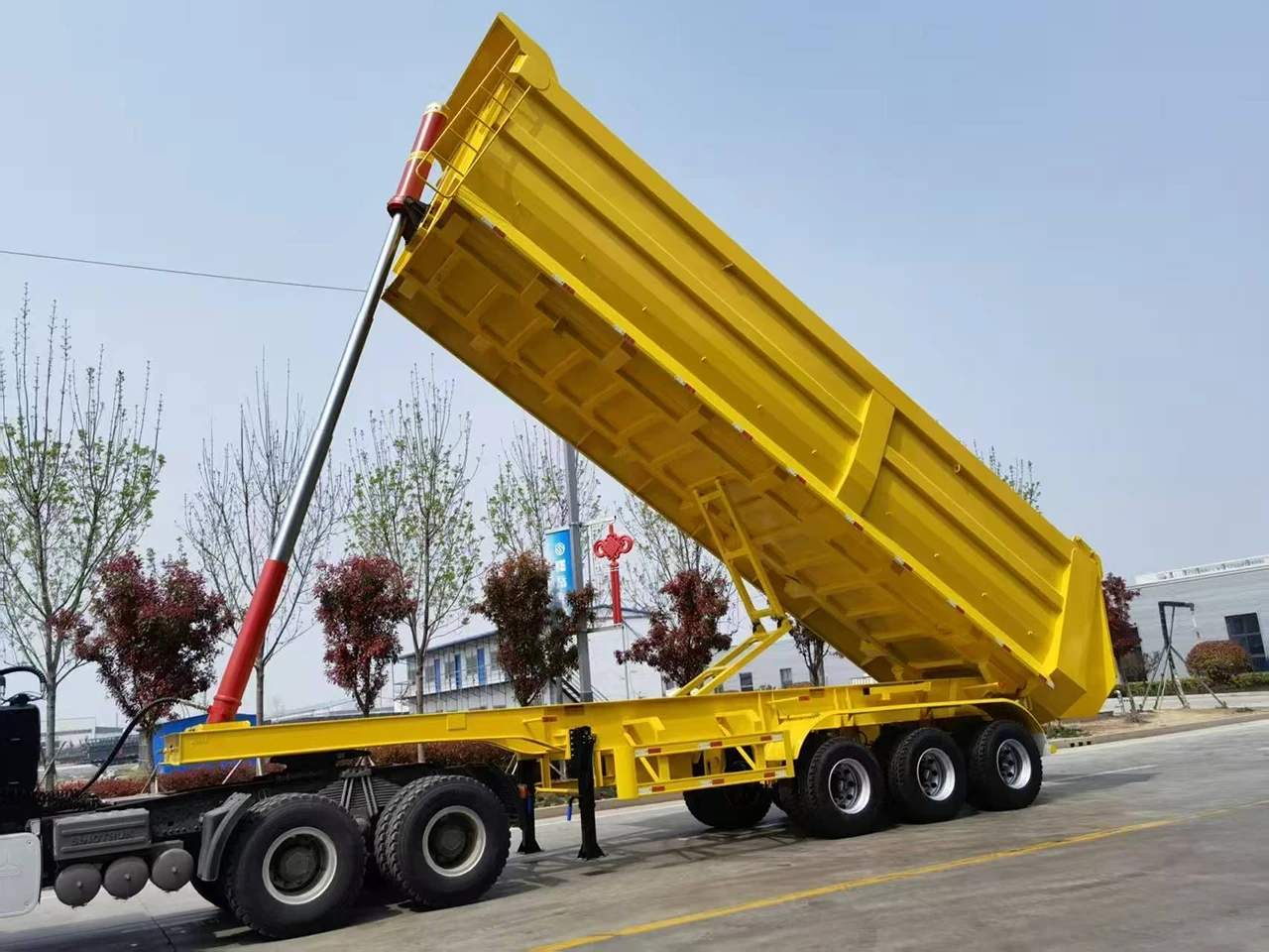
1.1 Rear Dump Trailer
- Unloading Direction: Body tilts backward, discharging material from the rear
- Ideal For: Mines, gravel yards, construction sites, and open areas
- Advantages: Simple structure, high lifting force, excellent stability, low maintenance cost
- Kales Application: Widely used in heavy-duty transport, equipped with a high-strength telescopic cylinder and lifting balance frame for smooth operation
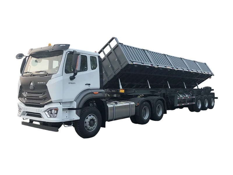
1.2 Side Dump Trailer
- Unloading Direction: Body tilts to the left or right side
- Ideal For: Narrow roads, railway corridors, trench backfilling, and single-side discharge scenarios
- Advantages: Flexible unloading, no need to turn around, high operational efficiency
- Kales Application: Features a multi-cylinder synchronized lifting system (typically 2–4 cylinders). Precision hydraulic control ensures smooth, twist-free tilting—ideal for extra-wide or extra-long bodies
✅ Whether rear dump or side dump, all Kales dump trailers use the same high-reliability hydraulic lifting system, ensuring component compatibility, easy maintenance, and adaptability to diverse global operating conditions.
2. Hydraulic System Structure of Kales Dump Trailers
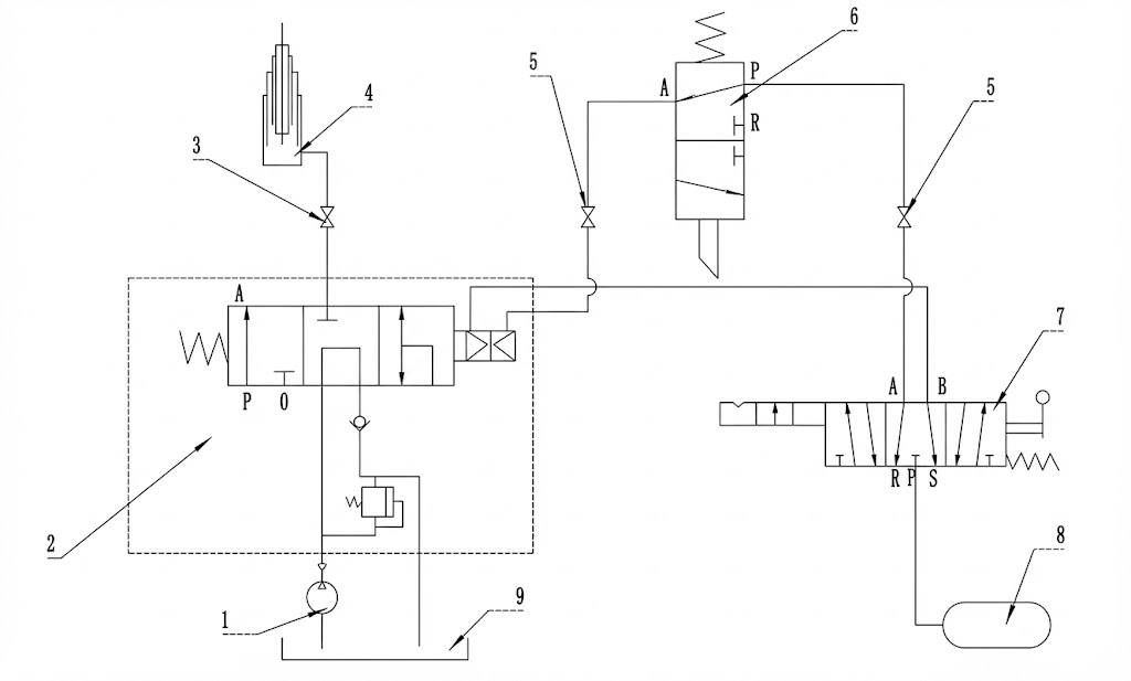
Kales dump trailers utilize a mature hydrostatic hydraulic system, known for high pressure, fast response, and precise control. The system consists of five core components:
2.1 Power Unit: PTO-Driven Hydraulic Pump
The hydraulic pump converts mechanical energy from the tractor’s engine into hydraulic energy. Kales standardizes a high-reliability external gear pump with:
- Rated working pressure: ~2.0 MPa
- Max speed: ≤2,500 RPM
- Driven directly by the tractor’s Power Take-Off (PTO) via the gearbox for efficient power transmission
2.2 Control Unit: Pneumatic-Hydraulic Integrated Valve Block
Kales employs a pneumatic-to-hydraulic control logic for simplicity and responsiveness:
- 3-Position, 6-Way Manual Pneumatic Control Valve: Operator selects “Lift / Neutral / Lower”
- 3-Position, 3-Way Lifting Control Valve: Receives air signals to switch oil flow direction
- Mechanical Limit Valve: Automatically restricts lift height to prevent over-extension
- Solenoid-Controlled PTO Valve: Ensures safe PTO engagement/disengagement
✅ All control components feature industrial-grade sealing, suitable for dusty, humid, or sub-zero environments.
2.3 Actuator: Telescopic Hydraulic Cylinders
Kales offers tailored cylinder configurations:
- Rear Dump Models: Single high-strength multi-stage cylinder, center-mounted with a balance frame for rigidity
- Side Dump Models: Multi-cylinder synchronized system (2–4 cylinders) with hydraulic balancing circuits to ensure uniform motion and prevent body twist or rollover
- All cylinders use a single-port design: High-pressure oil enters during lift; gravity returns oil during lowering—energy efficient
- Cylinder rods are hardened and chrome-plated for corrosion and wear resistance
2.4 Auxiliary Components
Includes high/low-pressure hydraulic hoses, pneumatic lines, ball valves, large-capacity oil tank, high-efficiency filters, and anti-loosening fittings—ensuring long-term leak-free operation.
2.5 Working Fluid
Use L-HM anti-wear hydraulic oil. Select the correct grade based on ambient temperature for optimal performance and system protection.
3. Kales Dump Trailer Operating Guide
Kales dump trailers operate via a “pneumatic command + hydraulic execution” logic. Follow this standardized procedure and safety protocol for safe, efficient unloading.
3.1 Pre-Operation Preparation
- Parking Requirements:
- Park on solid, level ground with a slope ≤3°.
- ❌ Never lift on slopes, soft soil, or uneven surfaces—risk of rollover is extremely high.
- Braking & Parking:
- Engage the parking brake and ensure the vehicle is fully stationary.
- Side Dump Specific Preparations (Side Dump Models Only):
- Before lifting, operate the side door lock control valve to unlock the side gate.
- If the body has manual lock hooks, release them manually before tilting.
- ⚠️ Warning: When opening side gates, stand outside the gate area to avoid injury from falling cargo.
- For left-side unloading (factory default is right-side):
- Remove the locking pin from the right-side tilt support,
- Insert it into the left-side support,
- Secure with a cotter pin,
- Open all left-side panels.
3.2 Lift Preparation
- Press the clutch pedal to disconnect drivetrain power.
- Engage the PTO switch (lever or button):
- ✅ Correct: With clutch depressed, engage PTO so gears mesh smoothly.
- ❌ Never engage PTO without pressing the clutch—this will damage transmission and PTO gears.
- Slowly release the clutch. Engine power now drives the hydraulic pump, generating high-pressure oil.
- At this stage, the directional control valve is in neutral (return-to-tank) position—no lifting occurs.
🔒 Note: Some models feature safety interlocks on PTO/lift switches. Press the safety button before turning the switch.
3.3 Lifting Procedure
- Initiate Lift:
- With the pump running steadily, move the pneumatic control valve to “Lift”.
- High-pressure oil flows through the directional valve into the cylinder, raising the body.
- Control Lifting Speed:
- Gently press the accelerator pedal to adjust engine RPM and pump output for smooth, controlled lift.
- ❌ Avoid sudden throttle input to prevent shock loading.
- Mid-Stroke Hold (Stop at Any Height):
- To pause at a specific angle (e.g., for cleaning sticky material):
- First, disengage the PTO (stop oil supply),
- Then return the control valve to neutral.
- The hydraulic circuit locks automatically—body remains stable at any position.
- To pause at a specific angle (e.g., for cleaning sticky material):
- Automatic Height Limit Protection:
- When the body reaches its designed maximum angle (typically ~20 cm between rear gate and ground), the built-in relief/flow-diverting valve in the cylinder opens automatically.
- High-pressure oil returns to the tank via the directional valve—lifting stops.
- ⚠️ Critical: If the limit valve pull-cord breaks, immediately stop lifting and repair. Failure to do so may cause “cylinder pull-out,” rendering the cylinder unable to lower and potentially causing permanent damage.
🔧 Safety Protocol for Limit Valve Adjustment:
Always use approved safety props and support bars to mechanically secure the body before any adjustment. Never rely solely on the hydraulic system for support.
3.4 Lowering Procedure
- Prepare for Lowering:
- After unloading, disengage the PTO switch to stop the pump.
- Move the control valve to the “Lower” position—this opens the return oil path.
- Control Descent Speed:
- The body lowers under gravity, with oil returning to the tank through the directional valve.
- By fine-adjusting the lever position, you can control descent speed or pause at any height.
- Side Dump Reset:
- Once the body is fully lowered, close the side gate and re-engage both pneumatic and manual locks.
⚠️ Absolute Prohibitions:
- ❌ Never lower under heavy load at high speed
- ❌ Never drive with the body raised
- ❌ Never operate the PTO while driving (will destroy the hydraulic pump)
3.5 Post-Operation Safety Check
- Verify no air leaks in pneumatic lines
- Confirm no hydraulic fluid leaks
- Ensure PTO engages/disengages smoothly with no abnormal noise
- Confirm body is fully seated and all locks (pneumatic + mechanical) are secured
3.6 Critical Safety Prohibitions (MUST FOLLOW)
| # | Safety Rule |
|---|---|
| 1 | ❌ Never overload or unevenly load the trailer |
| 2 | ❌ Never drive with PTO engaged |
| 3 | ❌ Never drive with the body raised |
| 4 | ❌ Never unload on slopes or unstable ground |
| 5 | ❌ Never rapidly lower a loaded body |
| 6 | ❌ Never allow personnel in the rollover zone during lift/lower |
| 7 | ❌ Never drive when the body is near or at maximum lift height—always lower completely first |
3.7 Routine Maintenance Reminder
- Lubrication: Grease all modified-component lubrication points (e.g., balance frame pins, lift brackets) with #2 lithium-based grease, 1–2 times per month.
- System Readiness: If the solenoid valve loses power or air pressure is insufficient, the cylinder will not respond. Always verify pneumatic and electrical systems before operation.
✅ Summary: Standardized operation = Safety + Efficiency + Long Equipment Life. Every lift is a test of professionalism.
4. Common Fault Diagnosis & Quick Troubleshooting
Kales dump trailers may experience hydraulic issues during long-term use. Below is a detailed, step-by-step guide for rapid diagnosis and repair.
4.1 Body Won’t Lift
This is the most frequent issue. Diagnose in this order: Electrical → Pneumatic → Hydraulic
4.1.1 Electrical Check
- The PTO is pneumatically controlled via a solenoid valve.
- With engine off, press the PTO switch:
- ✅ Normal: You hear a “click” (solenoid actuation) + “puff” (air exhaust)
- ❌ Fault: No sound → likely electrical issue (blown fuse, open/shorted solenoid coil, stuck solenoid)
- → Inspect wiring and replace faulty components.
4.1.2 Pneumatic Check
- System relies on compressed air. In normal operation, moving the lever produces a “puff” at exhaust ports.
- No sound?
- Disconnect inlet air line at pneumatic valve—check for system air pressure.
- ❌ No/low pressure → inspect air circuit (kinked line, frozen moisture in winter, or pinched hose).
- Air pressure OK?
- Disconnect “Lift” air line from pneumatic valve, move lever to “Lift”—check for airflow.
- ❌ No air → pneumatic valve failure (usually non-repairable; replace unit).
4.1.3 Hydraulic Check
- Limit Valve Test: With lever in “Lift”, disconnect both air lines from limit valve.
- ✅ Air flows → valve OK
- ❌ No air → valve stuck (common due to rust). Spray with penetrating oil—often resolves issue.
- Lift Valve Air Test: Disconnect “Lift” air line at lift valve.
- ❌ No air → blockage in air line between pneumatic and lift valves.
- Hydraulic Pressure Test:
- Connect pressure gauge to test port on lift valve. Engage PTO—system pressure should be ≥1.8 MPa.
- ❌ Low pressure → check:
- Hydraulic oil level
- Ball valve open?
- Low-pressure hose kinked?
- Gear pump damaged?
- ✅ Normal pressure but no lift → lift valve fault (stuck spool, low relief setting, air cylinder leakage). Disassemble and service.
4.2 Body Won’t Lower
Usually caused by pneumatic issues:
- Failed pneumatic valve
- Blocked or kinked air line
- Air leakage in lift valve’s pneumatic chamber
- Mechanical faults (e.g., bent cylinder, stuck spool) are extremely rare.
4.3 Slow Lifting
Common causes:
- Air leaks or kinked pneumatic lines
- Low gear pump output (worn pump)
- Air leakage in lift valve’s pneumatic actuator
4.4 Body Jitters During Lift
Most often due to low hydraulic oil level. Less commonly:
- Gear pump failure
- PTO malfunction (interrupted power transmission)
4.5 Slow Lowering
Primary cause:
- Air leaks or kinked pneumatic lines
- Adjustment: The lift valve has a hex-head lowering speed screw:
- Turn inward → faster descent
- Turn outward → slower descent
4.6 Body Drifts Down Automatically
⚠️ Critical Safety Hazard! Causes include:
- Internal leakage in lift valve
- Pneumatic chamber leakage in lift valve
- Faulty pneumatic control valve
- Severe cylinder seal failure
4.7 Oil Spray from Top of Hydraulic Tank
Caused by clogged return filter:
- High-pressure return oil ruptures filter housing
- Oil sprays inside tank top instead of returning to bottom
- → Replace entire return filter assembly and secure return line to tank bottom.
4.8 Leaks at Hydraulic Fittings
- All sealing washers are single-use. Always replace after disassembly.
- Ensure sealing surfaces are clean, flat, and free of debris or dents.
- Torque fittings to specification.
4.9 Oil Leaking from Pneumatic Valve
- Pneumatic valves should only carry air—oil indicates internal wear.
- Worn lift valve spool allows hydraulic oil to enter pneumatic chamber → oil exits via pneumatic valve.
- Key diagnostic clue: Oily residue on pneumatic valve = lift valve wear.
5. Kales Dump Trailer Operation & Maintenance Recommendations
5.1 Hydraulic System Maintenance
5.1.1 Hydraulic Oil Selection & Replacement
- Winter (low temps): Use ISO VG 32 L-HM anti-wear hydraulic oil (lower viscosity for cold starts)
- Summer (high temps): Use ISO VG 46 L-HM anti-wear hydraulic oil (higher viscosity for film strength)
- ❌ Never mix brands or grades
Replacement Intervals:
- Hydraulic oil: Every 6 months (every 3 months in harsh conditions)
- Always clean tank interior before refilling
5.1.2 Seal Inspection & Replacement
- Inspect all hydraulic seals before winter
- Replace if cracked, hardened, or leaking
5.1.3 Hydraulic Hose Inspection
- Check fittings for looseness or leaks
- Inspect rubber hoses for cracks, bulges, or abrasion—replace if damaged
5.1.4 Winter-Specific Care
- Clean tank surface and filler cap to prevent contamination
- Verify PTO gear engagement is smooth and noise-free
- Wipe cylinder rods; inspect for scratches or dents—replace if damaged
5.2 General Maintenance
5.2.1 Bolt Tightness
- Regularly inspect and torque all structural bolts
5.2.2 Brake System
- Check brake chambers for air leaks
- Inspect brake linings—replace if worn
- Ensure braking performance is reliable at all times
5.2.3 Lubrication Points
- Grease axle pins, kingpins, and all rotating joints regularly
5.2.4 Tailgate Locking Mechanism
- Ensure secure engagement—repair if loose or misaligned
5.2.5 Main Frame & Lift Frame
- Inspect for cracks or weld separation
- Repair immediately if damage is found
Conclusion: Professional Operation + Scientific Maintenance = Kales Efficiency
Whether rear dump or side dump, Kales dump trailers deliver safety, reliability, and efficiency through a robust hydraulic system. By following standardized procedures and proactive maintenance, you will:
- Reduce unplanned downtime
- Extend trailer service life
- Enhance operational safety
- Lower total cost of ownership
🔧 Need technical support? Contact our service team for expert assistance!