Foreword: Designed for professional drivers and fleet managers, this manual provides the essential SOPs (Standard Operating Procedures) for the safe operation of Kales Fuel Tanker Trailers. Adherence to these guidelines ensures compliance with international HAZMAT transport regulations.
Technical basis and safety scope
How this fuel tanker manual is supported
This manual is based on Kales export fuel tanker configuration, the API bottom-loading hardware described in the article, and dangerous-goods operating references already used in the text: API RP1004 for bottom-loading couplers, ADR/RID operating concepts, and DOT406 cargo tank concepts for tank integrity, vapor recovery, static grounding and compartment leak testing.
For external safety context, the guide references OSHA 1910.106 for flammable liquids, PHMSA 49 CFR 178.345 cargo tank specifications, PHMSA 49 CFR 178.346 DOT 406 cargo tank requirements, PHMSA 49 CFR 180.407 cargo tank inspection and testing, and the U.S. CSB Barton Solvents static-spark investigation. These sources support the same field priorities: bonding and grounding, overfill prevention, vapor control, leak testing, compartment integrity and documented inspection.
The figures in this guide are operating references for trained fleets: P/V vent working pressure around +6 to +8 kPa / -2 to -3 kPa, pneumatic interlock pressure around 0.35-0.5 MPa, grounding continuity below 10 Ohms, and pneumatic leak testing at 35 kPa. Always follow the vehicle documents, terminal rules and local hazardous-goods law for the exact unit.
1. Core Systems Overview
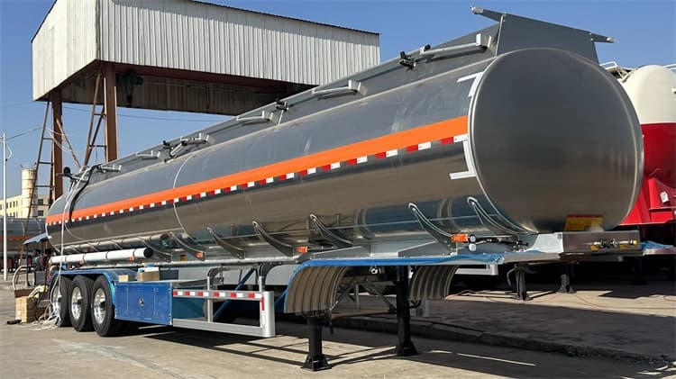
1.1 🛢️ Tank Body & Construction
- Material Standards: High-tensile Carbon Steel (Q345R), Stainless Steel, or Aluminum Alloy (5083). Compliant with ADR/RID and ISO standards for dangerous goods transport.
- Compatible Media: Gasoline (Petrol), Diesel, Kerosene, and Jet Fuel.ℹ️ Note: For transporting edible oils or specific chemicals, ensure seals (gaskets) and lubricants are food-grade or chemically compatible. Never cross-contaminate without validation.
- Anti-Surge Design: Equipped with internal Baffles (Thickness ≥4mm, flow area >20%) to minimize liquid surge and improve vehicle stability.
- Capacity: 20,000L – 80,000L, available in Single or Multi-Compartment configurations.
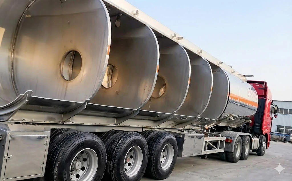
- Cross-sectional diagram of the bulkheads and baffles in the Kales fuel tank semi-trailer
1.2 ⚙️ Manhole Assembly (Top Loading System)
Located on the tank top, the standard Euro-style Manhole (DN500) integrates:
- Breather Valve (P/V Vent): Dual-mode Pressure/Vacuum relief.
- Working Pressure: +6~+8 kPa (Pressure) / -2~-3 kPa (Vacuum).
- Emergency Venting: 21~32 kPa.
- Safety Interlock: The cover cannot be opened unless residual tank pressure is safe.
- Overfill Prevention: Integrated with optic/thermistor sensors to trigger high-level alarms and shut off loading automatically.
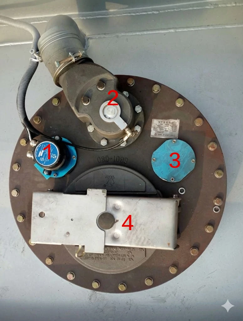
European-style manhole cover with integrated pressure 1.Overfill prevention probe 2.Vapor recovery valve 3.Gauging hatch (or dip tube opening) 4.Manhole cover with integrated Breather Valve and Safety Interlock
1.3 🔋 Bottom Loading System (API Standard)
The core system for closed-loop, environmentally friendly loading operations. Fully compliant with API RP1004.
- Emergency Foot Valve (Internal Valve): Pneumatically operated. Features a shear groove that snaps off during a collision, keeping the tank sealed to prevent spillage.
- API Adapter Valve: The standard 4-inch valve with a 70° nose angle for dry-break coupling. Uses FKM (Viton) seals for fuel resistance.
- Vapor Recovery Valve: Interlocked to open with the Foot Valve, returning volatile vapors to the terminal instead of venting to the atmosphere.
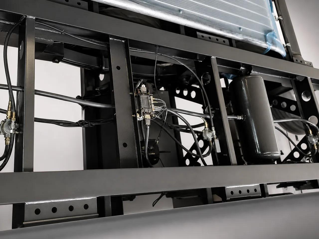
- Pneumatic Control Block: Centralizes control for all valves, including the Master Air Valve.
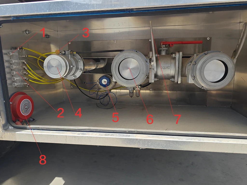
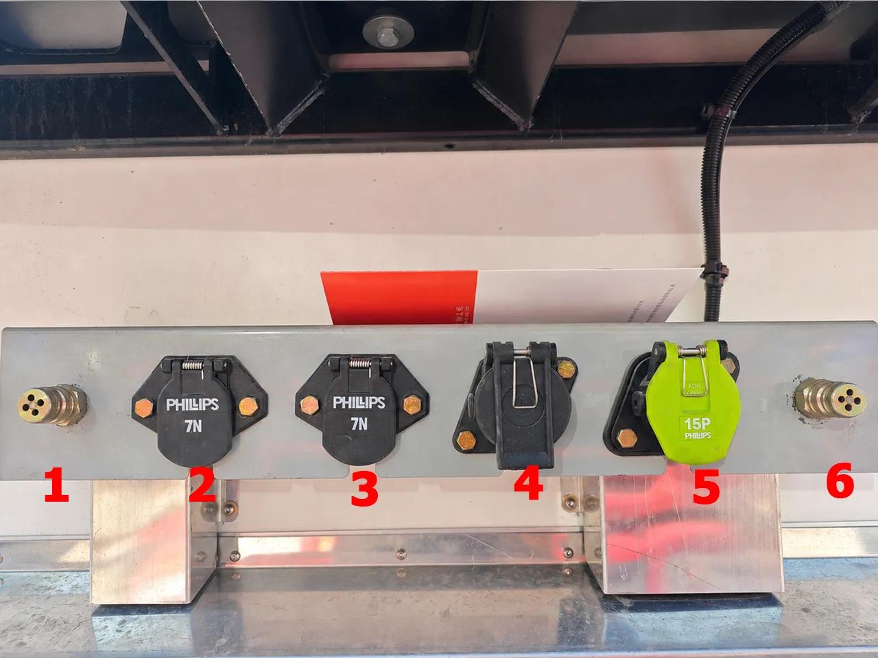
Valve Box Components Legend:
- Master Air Valve: Activates the main pneumatic system.
- Compartment Switches: Pneumatic controls for individual Emergency Foot Valves.
- Vapor Recovery Switch: Opens the top vents (Interlocked with Master Valve).
- Vapor Recovery Valve: Outlet for recovering vapors during loading.
- Overfill Prevention Socket: Connection point for the terminal’s anti-overfill monitor.
- API Adapter Valve: Standard 4″ connection for bottom loading/unloading.
- API Valve Handle: Manually controls the valve opening and flow rate.
- Static Grounding Pin & Clamp: Essential connection point for static dissipation.
2. Standard Operating Procedures (SOP)
2.1 ⛽ Loading Procedure (Bottom Loading)
A. Pre-Loading Checks
- 🛑 Park & Secure: Engine off, parking brake set, wheel chocks in place.
- ⚡ Static Grounding (CRITICAL): Connect the Bonding Cable to the terminal ground. Ensure the continuity light is green.*Wait 15 minutes after parking for static dissipation before connecting.
- 🔄 System Reset: Ensure all valves are closed and the air pressure gauge reads 0.35–0.5 MPa (50-70 psi).
B. Loading Execution
- Connections:
- Connect Overfill Probe Socket (Ensure no “Wet” alarm).
- Connect Vapor Recovery Hose.
- Connect Loading Arm to the API Adapter (Lock securely).
- Open Master Air Valve:
- ✅ Action: Pull the “Master” switch.
- 💡 Function: Engages the pneumatic system and forces the Vapor Vents open to balance tank pressure.
- Open Product Line:
- Actuate the Foot Valve switch for the specific compartment.
- Manually open the API Valve Handle.
- Start Loading: Follow terminal procedures. Monitor the Emergency Shut Down (ESD) button.
- Loading Sequence:
- Recommended: Load evenly (e.g., Center first, or Front/Rear balanced).
- ⚠️ PROHIBITED: Driving with a full load in only the front or rear compartment (prevents Kingpin/Suspension damage).
C. Post-Loading Disconnection
- Close & Disconnect: Once the pump stops, close the Foot Valve first, then the API Valve. Disconnect hoses.
- Final Step: Disconnect the Grounding Cable last.
2.2 💧 Unloading Procedure (Gravity Drop)
🛑 DANGER: Vacuum Collapse Warning
Liquid discharging creates a massive vacuum inside the tank.
NEVER unload without opening the Master Air Valve (Vapor Vents).
Failure to vent the tank will cause the tank body to implode (collapse) instantly.
Execution Steps:
- Hose Connection: Connect Vapor Hose (if available) first, then the Discharge Hose.
- Equalize Pressure: Open the Master Air Valve.Check: Listen for the “hiss” or mechanical sound of the Vapor Vents opening on top.
- Discharge: Open the Foot Valve, then open the Manual Discharge Valve.
- Monitor: Never leave the vehicle unattended. Watch the sight glass.
- Drain & Finish: Tilt the hose to drain residue into the storage tank. Close valves in order: Foot Valve ➔ Manual Valve. Disconnect hoses.
2.3 🚛 Special Operations
🔩 Lift Axle Operation
- Permitted: Only when the trailer is Unloaded (Empty).
- Prohibited: NEVER lift the axle when carrying a load.
↩️ Self-Steering Axle (Reversing)
- Procedure: Before reversing, drive forward 3–5 meters to straighten the wheels. Shift into Reverse and ensure the Locking Pin is engaged.
- ⚠️ Warranty Void: Reversing without locking the steering axle will cause severe damage to the steering mechanism and tires. This is NOT covered under warranty.
3. API Bottom-Loading Coupling Specifications
Bottom loading via API couplers is the industry standard for safe fuel transfer. Standardizing these connections ensures that any terminal arm can mate securely without leaking. The Kales bottom-loading suite is manufactured in strict accordance with the API RP1004 specification.
The API adapter’s profile must be measured periodically to prevent connection failures. Worn adapters will bypass the coupler latch locks, allowing the arm to disconnect under pressure, resulting in high-volume fuel spills.
| Parameter Spec | API RP1004 Standard Limit | Kales Factory Specification | Field Tolerance & Verification Method |
|---|---|---|---|
| Adapter Nose Diameter | 101.6mm (4.000 inches) | 101.55mm +/- 0.05mm | Discard adapter if diameter measures <100.8mm (3.968″). Measure with caliper. |
| Nose Angle / Bevel | 70 degrees | 70.0 degrees +/- 0.5° | Verify profile using a go/no-go gauge. Inspect for nicks on locking lip. |
| Max Flow Rating | 2,400 L/min (635 GPM) | 2,500 L/min | Do not exceed loading pressure of 5.0 Bar (72 PSI) at the terminal arm. |
| Poppet Leakage Threshold | Zero visible leakage | <0.05 ml per disconnect | Replace Viton seal ring if leakage exceeds 3 drops per disconnect cycle. |
| Interlock Air Pressure | 0.35 – 0.70 MPa | 0.50 MPa (5.0 Bar) | Inspect pneumatic logic block pressure gauge. The system must lock out if pressure is <0.30 MPa. |
4. Closed-Loop Vapor Recovery System
During loading or unloading, fuel vapors (which contain volatile organic compounds, VOCs) must not be vented to the environment. The closed-loop vapor recovery system routes these vapors back to the terminal or storage tank. If this system is restricted, the tank will experience either over-pressurization during loading or structural vacuum collapse during gravity unloading.
4.1. System Components and Pipe Diameter
The vapor recovery system starts at the top of each compartment, where a pneumatically controlled vapor vent valve is mounted on the manhole cover. These valves vent into a common 100mm (4-inch) aluminum pipe manifold running along the top of the tank.
This pipe descends at the front of the trailer, terminating in a 4-inch API vapor adapter valve in the main discharge box. An integrated check valve prevents reverse flow from the terminal. A flame arrestor screen is installed inside the manifold to prevent external ignition sources from travelling into the tank compartments.
4.2. Condensate Trap Maintenance
As warm fuel vapors cool inside the vapor pipe manifold, they condense back into liquid fuel. This liquid settles at the lowest point of the vapor recovery pipe, near the bottom discharge valve.
Required Maintenance: Operators must open the vapor recovery pipe drain valve weekly. If liquid fuel is allowed to accumulate, it will block the airflow, creating high backpressure that triggers the terminal’s emergency shut-off sensor during loading.
5. Static Grounding & Bonding Verification
Fuel flowing through pipes generates electrostatic charges. If these charges accumulate on the tank body, they can create a high-voltage spark when a hose or coupling is disconnected, igniting fuel vapors. Static grounding is the single most critical safety protocol during fuel transfer.
5.1. Grounding vs. Bonding
- Grounding: Connects the trailer chassis directly to the earth (ground rod) to bleed off accumulated static charge.
- Bonding: Connects the tractor, trailer chassis, and loading terminal piping together electrically to ensure they are at the same electrical potential, preventing sparks when hoses are connected.
5.2. Testing Grounding Continuity
Do not assume the grounding strap is doing its job. Check the electrical resistance of the grounding circuit using this procedure:
- Locate the brass grounding pins on the trailer’s front nosebox and the copper grounding strap at the rear.
- Set your digital multimeter (DMM) to the Ohms (Ω) scale.
- Measure the resistance between the API adapter valve body and the copper grounding strap touching the ground.
- The resistance must measure less than 10 Ohms.
Diagnosis: If the resistance is greater than 10 Ohms, check for paint or rust on the grounding bolt connections. Clean the mounting bolts down to bare metal and re-test. Replace the grounding copper braid if it is frayed or corroded.
6. Tank Integrity & Compartment Leak Testing Protocol
To comply with dangerous goods regulations (ADR / DOT406), the structural integrity of the tank shell and individual bulkheads must be tested annually. Leakage between compartments (bulkhead cracks) causes product cross-contamination (e.g., diesel mixing with premium gasoline), which is a severe safety and commercial risk.
6.1. Pressure Decay Leak Test (Pneumatic Test)
Never exceed the test pressure of 35 kPa (5.0 PSI / 0.35 Bar) during pneumatic testing. Applying high air pressure to a large tank creates massive stored energy. Over-pressurizing can cause the tank shell to rupture, risking fatal injuries. Use a pressure regulator and safety relief valve on the test air line.
Procedure:
- Drain all compartments completely and flush them to ensure they are gas-free.
- Close all discharge valves, manhole covers, and vapor vents. Isolation plugs must be installed in place of the breather valves.
- Connect an air test manifold to the compartment’s vapor recovery port.
- Slowly pressurize the compartment to 35 kPa (5.0 PSI). Isolate the air supply.
- Monitor the pressure gauge for a period of 5 minutes.
Pass/Fail Specs: The pressure drop must not exceed 1.0 kPa (0.15 PSI) over the 5-minute test duration. If the pressure drops faster, apply a soap-and-water solution to all weld seams, manhole gaskets, and valve flanges. The presence of bubbles will locate the leak path. Repeat this test for each compartment individually while adjacent compartments are at zero pressure to verify bulkhead integrity.
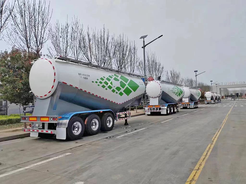
Export operation note: fuel distribution routes and hot climates
For export fleets working between terminals, depots, mines and filling stations, safety depends on routine discipline more than on one single component. Heat, dust, rough roads and mixed driver teams make small failures more likely: dry or cracked gaskets, loose U-bolts, blocked vapor lines, corroded grounding points and worn API adapter seals.
When ordering a fuel tanker, include spare FKM/Viton seals, API adapter gaskets, grounding straps, P/V vent service parts, fire-extinguisher brackets, pneumatic fittings and valve box labels in the initial spare-parts package. These parts support safer field maintenance without improvising around fuel vapor and static electricity.
Daily driver checklist before loading fuel
- Static control: inspect grounding strap, grounding pin and terminal continuity light before any product connection.
- Vapor control: confirm vapor vents open when the master air valve is activated and drain condensate from the vapor line as scheduled.
- Valve control: check API adapter seal, emergency foot valve response, overfill socket condition and compartment switch labels.
- Road safety: verify fire extinguisher tag, tire condition, U-bolts, suspension pads and that load is balanced by compartment.
7. Maintenance & Safety Checklist
7.1 🛠️ Preventive Maintenance Schedule
| Component | Action Required | Frequency |
|---|---|---|
| U-Bolts | Re-torque after the first 50-100km (Loaded) to compensate for rubber settling. Target torque is 300 Nm. | New Trailer + Monthly |
| Static Grounding | Check the Earthing Strap for contact with the ground and conductivity. Measure resistance. | 📅 Every Trip |
| Valves | Ensure all valves are fully closed. Do not leave in “Half-Open” position. | 📅 Daily |
| Pneumatics | Clean air filters/strainers. Check system pressure. Drain condensate from separator. | 📅 Weekly |
| Breather Valves | Professional inspection for sealing and pressure settings. Check spring tension. | 📅 Quarterly |
| Extinguisher | Check pressure gauge (Green zone) and hose condition. Verify inspection tag. | 📅 Monthly |
7.2 🚫 Critical Safety Rules
- No Overloading: Adhere strictly to the Gross Vehicle Weight (GVW) and compartment limits.
- No Ignition Sources: No smoking. Use only Non-Sparking Tools when working on the tank or valves.
- Confined Space Entry: NEVER enter the tank without: ① Full Depressurization ② Cleaning/Degassing ③ Forced Ventilation ④ Gas Testing ⑤ A Safety Spotter.
- Winter Precautions: If valves are frozen, DO NOT use open flames. Use steam or hot water to thaw.
Transfer Control: Attendant, Emergency Stop and Disconnect Sequence
Fuel tanker risk rises during loading and unloading because liquid movement, vapor displacement and hose connection all happen at the same time. Treat every transfer as a controlled operation, not a background task. One trained person should own the transfer from wheel chocking to final cap closure, and that person must be able to stop flow immediately.
The control logic is supported by recognized safety references. OSHA 1910.106 addresses flammable-liquid handling, the PHMSA cargo tank inspection rule reinforces documented tank integrity, and the CSB Barton Solvents investigation shows why static bonding, grounding and equipment suitability cannot be treated as paperwork.
- Before flow: chock wheels, set brakes, shut down unauthorized ignition sources, connect grounding/bonding, verify overfill protection and confirm the correct compartment/product match.
- During flow: keep the attendant at the loading point, watch vapor line behavior, check API adapter leakage, monitor compartment level and stop if odor, alarm, pressure surge or abnormal hose movement appears.
- Before disconnect: close flow first, allow line drain-down, close compartment valves, depressurize as specified by the terminal, then remove loading arm, vapor hose and ground connection in the approved sequence.
- Before dispatch: confirm caps are locked, seals are installed, placards match the cargo, spill kit and extinguisher are present, and the driver has the terminal release record.
For repeatable fleet control, pair this transfer record with the Kales semi-trailer maintenance manual and the semi-trailer troubleshooting guide. Electrical faults, brake defects and grounding failures should be solved before the tanker enters a fuel terminal.
Related Kales resources
Need technical support or genuine tanker spare parts?
Fuel tanker maintenance should not rely on improvised parts. Kales can help confirm API adapter parts, valve seals, grounding components, vapor recovery fittings and other export tanker spares for your exact configuration.
This manual is based on the standard export configuration of Kales Vehicle Co., Ltd. Actual vehicle specifications may vary based on custom orders. Please refer to the technical documents delivered with your specific vehicle.