This comprehensive guide is designed for operators and fleet managers using Kales Tipper Semi Trailers. From understanding the advanced hydraulic tipping system to mastering safe unloading procedures and performing routine maintenance, this manual ensures maximum operational efficiency, safety, and longevity for your heavy-duty transport equipment.
Technical basis and safety scope
How this tipper trailer manual is supported
This manual is based on Kales rear and side tipper operating practice, the hydraulic diagrams already shown in the article, and the pressure and stability limits stated in the guide. Key references include the hydraulic working range of 190-220 bar, relief-valve adjustment target of 190-200 bar under load, maximum lateral slope of 3 degrees, maximum wind speed of 30 km/h, and the requirement to dump only on firm, level ground.
The safety basis is reinforced by public references on dump-body and workplace transport risk: NIOSH guidance on preventing injuries and deaths of dump truck operators, HSE guidance on workplace vehicle overturns, HSE quarry tipping-point guidance, HSE guidance on high-pressure hydraulic fluid injection, and an OSHA accident record involving a raised dump body. These sources support the same operating rule: assess the ground first, keep the tractor-trailer straight, stay clear of the raised body, and stop lifting if the load sticks or the body leans.
Use this as an operator and maintenance guide, not as a replacement for the vehicle delivery documents. Before lifting any body, the driver must confirm PTO engagement, air pressure, cylinder condition, rear-door or side-gate locking, tractor-trailer alignment, ground bearing capacity and an exclusion zone around the trailer.
1. Choosing the Right Kales Tipper: Rear vs. Side Tipping Trailer
Selecting the correct unloading method is crucial for mining and construction logistics. Kales offers specialized tipping semi trailers designed for robust performance on rough terrain.
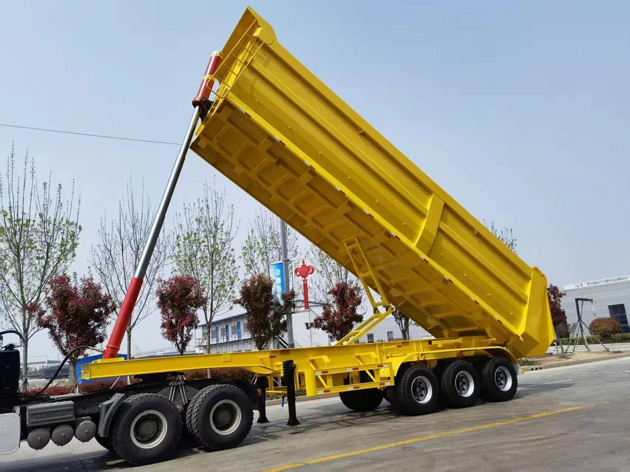
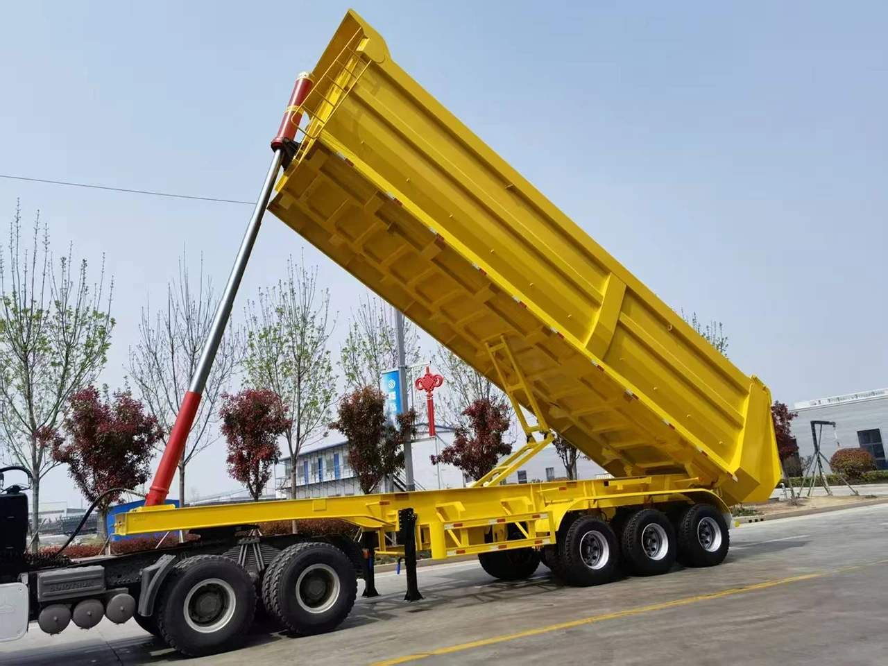
1.1 Rear Tipper Trailer (End Dump)
- Mechanism: The cargo box tilts backward, discharging material from the rear tailgate using a powerful telescopic cylinder.
- Best Applications: Mining transport, stone quarries, gravel yards, and heavy construction sites.
- Kales Features: Built with a heavy-duty chassis, front-mounted lifting cylinder, and a reinforced balance frame for superior stability during off-road operations.
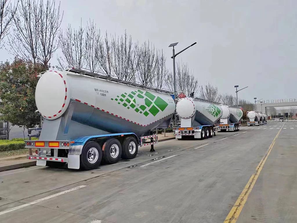
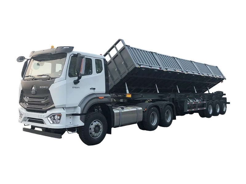
1.2 Side Tipper Trailer (Side Tipping Semi Trailer)
- Mechanism: The body tilts to either the left or right side, ideal for efficient roadside discharge.
- Best Applications: Narrow railway projects, road construction, and sites with height limitations where a rear dump trailer cannot operate.
- Kales Features: Utilizes an advanced multi-cylinder synchronized tipping system. Precision hydraulic balancing ensures twist-free tilting even with uneven loads.
Buyer selection note: rear tipper or side tipper?
Rear tippers and side tippers solve different site problems. A rear dump trailer is usually preferred for sand, aggregate, coal and quarry work where there is enough straight space behind the vehicle. A side tipper is useful for windrow discharge, road construction and narrow unloading zones, but it needs stricter attention to side slope and gate locking.
- Choose rear tipping when payload concentration, simple structure and deep dump piles matter most.
- Choose side tipping when fast linear discharge along a road, berm or stockpile is more important.
- Check maintenance capacity before ordering side tippers, because hinges, side cylinders and locking mechanisms add inspection points.
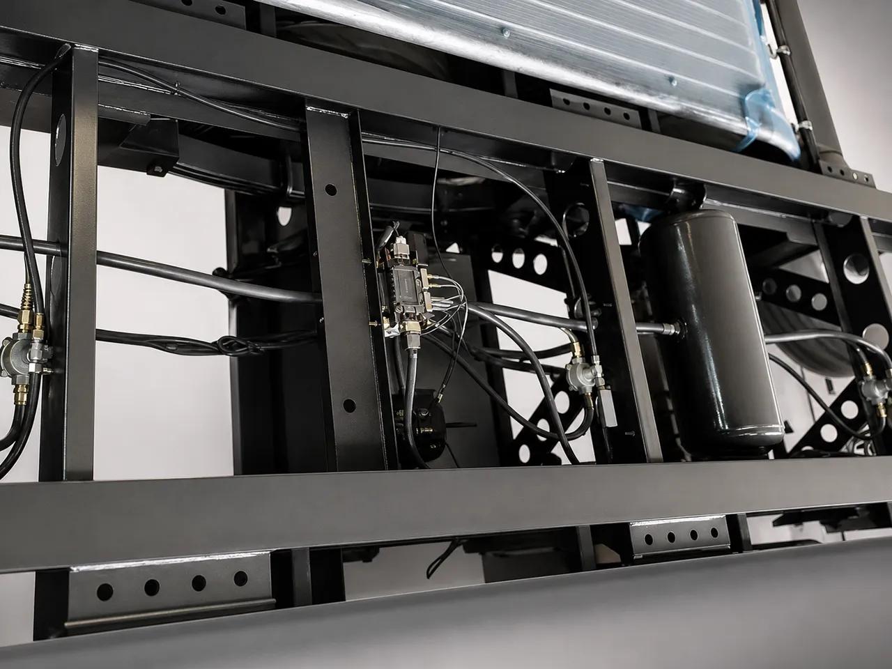
2. The Core: Kales Hydraulic Tipping System Explained
Kales tipper trailers rely on a mature high-pressure hydraulic system (~18-22 MPa / 180-220 Bar), known for rapid response and precise lifting control under heavy loads.
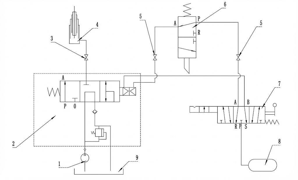
Rear Tipper Hydraulic Principle Diagram
1. Gear Pump (Hydraulic Power)
2. Pneumatic Control Valve
3. PTO (Power Take-Off)
4. Telescopic Lifting Cylinder
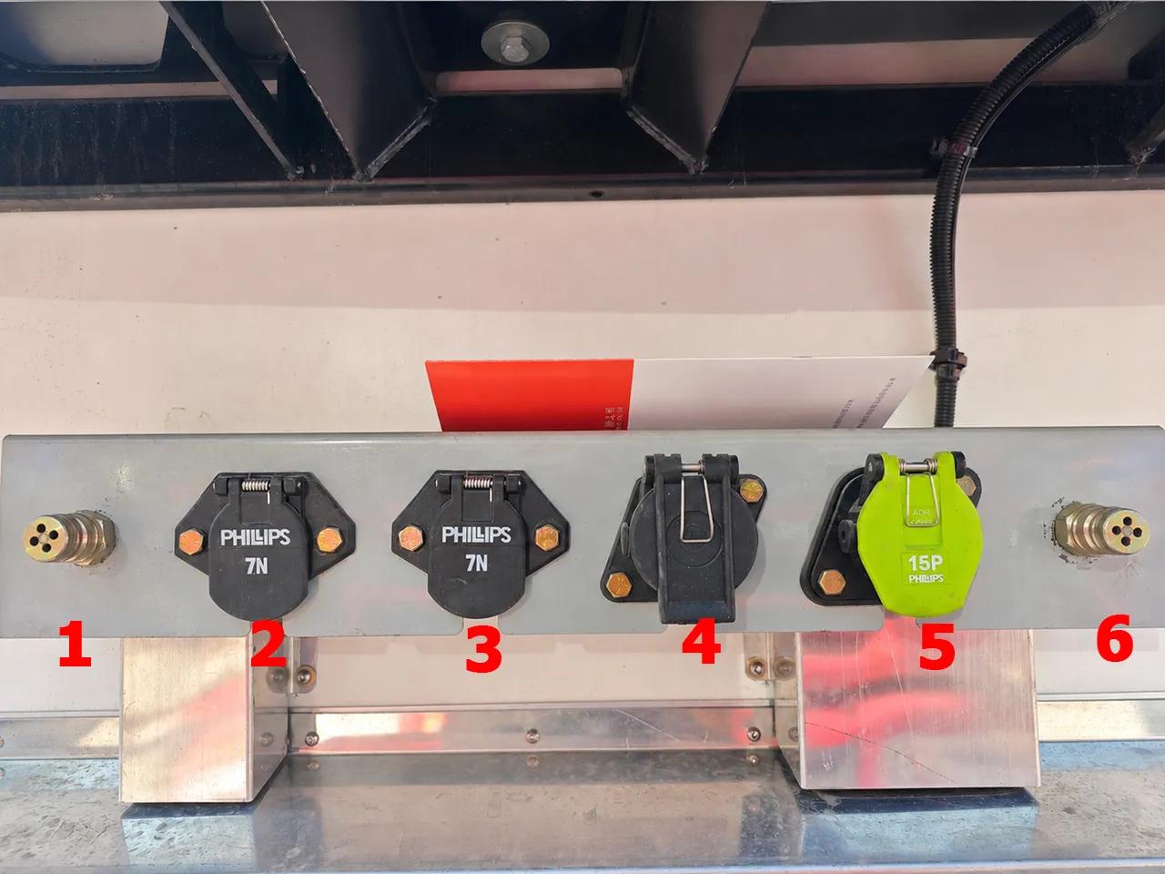
5. Quick Coupling Fitting
6. Limit Valve (Safety Stop)
7. Manual Cab Control
8. Air Source
9. Hydraulic Oil Tank
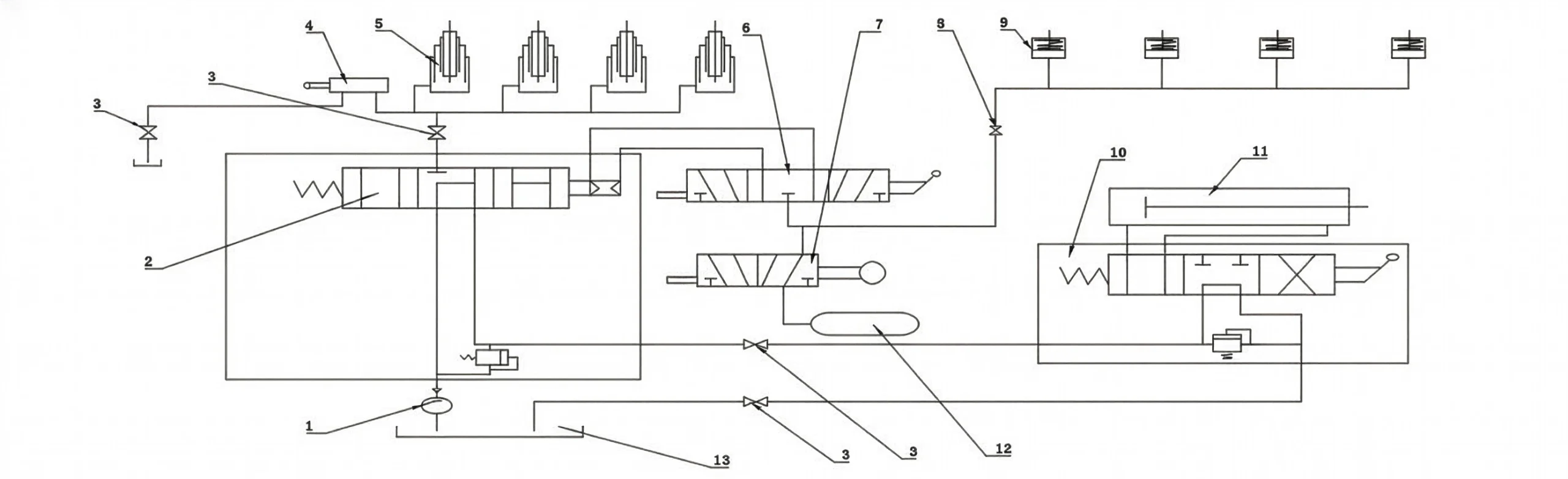
Side Tipper Hydraulic Principle Diagram
1. Hydraulic Pump
2. Directional Control Valve
3. PTO Unit
4. Hydraulic Limit Valve
5. Side Shift Cylinders
6. Tipping Control Valve
7. Side Door Locking Cylinder
8. Pneumatic Fitting
Key Hydraulic Components
- Power Unit (PTO Pump): Connects to the truck tractor gearbox to drive fluid flow.
- Control Unit (Valve Block): The “brain” of the tipping system.
- In-Cab Valve: Manual lever (Lift / Neutral / Lower).
- Limit Valve: Automatically stops the tipper body at max angle to prevent cylinder over-extension.
- Actuator (Hydraulic Cylinders): Hardened, chrome-plated cylinders designed for heavy-duty cycles and harsh environments.
3. Step-by-Step Operating Guide
- Park on solid, level ground (Slope ≤3°). Never dump on soft soil or uneven terrain.
- Engage the tractor parking brake completely.
- Ensure no overhead obstructions (power lines, bridges) typically found in construction zones.
3.1 Preparation (Side Tippers Only)
- Unlock the side gate using the pneumatic switch.
- Manually release any mechanical safety hooks on the cargo body.
- Check hinge pins: Ensure pins are locked on the correct side for discharge.
3.2 Lifting the Trailer Body
- Depress clutch pedal and engage PTO switch. Slowly release clutch.
- Move in-cab lever to “LIFT”.
- Gently increase engine RPM to control lift speed. Smooth operation prevents chassis stress.
- To pause: Disengage PTO and move lever to “Neutral”.
3.3 Lowering the Trailer Body
- Disengage PTO.
- Move control lever to “LOWER”.
- Gravity will lower the tipper box. Control descent speed by feathering the lever.
4. Troubleshooting: Tipper Hydraulic Faults
Use this guide to diagnose common issues with your tipping semi trailer.
| Symptom | Most Likely Cause | Quick Check Action |
|---|---|---|
| Tipper Won’t Lift | Electrical Issue (PTO) | Check fuse; Listen for solenoid “click” when engaging PTO. |
| Pneumatic Issue | Check truck air pressure; Check for blocked air lines to the control valve. | |
| Hydraulic Issue | Check if Limit Valve is stuck. Check hydraulic oil level. | |
| Tipper Won’t Lower | Pneumatic Control Failure | Check air lines on the lowering side of the valve. Check for stuck main spool. |
| Slow Lifting Speed | Pump Wear / Air Leaks | Check engine RPM; Listen for air hissing; Check gear pump condition and relief pressure. |
| Body Vibration/Jitters | Low Hydraulic Oil / Aeration | Stop immediately. Check oil tank sight glass to prevent pump cavitation. Bleed air from cylinders. |
5. Hydraulic Pressure Diagnostics & Relief Valve Calibration
The hydraulic lifting mechanism of Kales rear and side tippers is a high-performance system operating at peak pressures between 190 Bar (19 MPa) and 220 Bar (22 MPa). Operating outside these safety limits can either render the trailer incapable of lifting its rated payload or lead to catastrophic component failure, such as ruptured steel hoses or damaged cylinder stages.
5.1. Pressure Measurement Procedure
To verify the operating pressure of the hydraulic system, follow this testing procedure:
- Locate the high-pressure test port on the side of the main pneumatic directional control valve (tipping valve).
- Connect a calibrated 0-400 Bar (0-40 MPa) fluid-filled pressure gauge to the test port using a high-pressure test hose.
- Fill the tipper trailer to its maximum rated capacity.
- Engage the PTO, place the cab lever in the “LIFT” position, and monitor the pressure gauge as the cylinder starts its primary telescopic stage.
- The pressure should rise rapidly, peaking as the cylinder lifts the heaviest initial load, and then stabilize.
Diagnosis: If the pressure does not exceed 150 Bar and the cylinder fails to lift, the relief valve is set too low or the gear pump has internal wear, letting oil bypass the gears. If the pressure exceeds 240 Bar, shut off the PTO immediately. High pressure will damage the seal rings of the cylinder stages.
5.2. Adjusting the System Relief Valve
If adjustments are needed, locate the pressure relief adjustment screw on the tipping valve block:
- Loosen the locking nut.
- Using an Allen key, turn the adjustment screw clockwise to increase the relief pressure (typically 1 turn increases pressure by approx. 30 Bar).
- Turn counter-clockwise to decrease the pressure setting.
- Tighten the locking nut once the target pressure of 190-200 Bar under load is achieved.
6. Safe Dumping Ground Assessment Guide
A dump trailer is highly vulnerable to tipping over during the last stages of the lift. As the cylinder extends, the trailer’s center of gravity moves upward and backward. If the ground under the tires settles unevenly, even by a few inches, the trailer will lean, twisting the chassis and causing a rollover.
6.1. Soil Bearing Capacity Assessment
Before initiating any dump operation, the operator must assess the ground condition. Different soil types have varying load-bearing capacities under heavy wheel loads.
| Ground Surface Type | Estimated Bearing Capacity | Safety Risk Level | Operator Action / Precautions |
|---|---|---|---|
| Compacted Gravel / Asphalt | High (>300 kPa) | Low Risk | Standard operation. Ensure tractor and trailer axles are in a straight line. |
| Dry, Compacted Soil / Clay | Medium (150-250 kPa) | Moderate Risk | Check for hidden underground voids. Re-check level after the first cylinder stage extends. |
| Loose Sand / Mud / Wet Fill | Low (<100 kPa) | Critical Danger | Do not dump. Tires will sink unevenly as weight transfers backward. Reposition to compacted ground. |
| Freshly Backfilled Excavations | Extremely Low | Critical Danger | Prohibited. The edge of the bank can collapse under the trailer’s rear dual wheels. Keep axles at least 3 meters away from slope edges. |
6.2. Environmental and Operation Limits
- Maximum Lateral Slope: 3 degrees. If the trailer leans more than 3 degrees sideways, do not attempt to lift the body.
- Maximum Wind Speed: 30 km/h (18 mph). High crosswinds acting on the large surface area of an extended tipper body create massive tipping forces.
- Axle Alignment: The tractor and trailer must be aligned in a straight line. Jackknifed dump units are significantly more prone to rollover because the tractor cannot stabilize the trailer sideways.
7. Telescopic Cylinder (Hyva / Kales OEM) Maintenance & Seals
The front-mounted telescopic cylinder is the most valuable and highly stressed component of the tipper. Kales utilizes premium multi-stage cylinders (typically 4 or 5 stages depending on body length) with hard-chrome plating on all sliding sleeves.
7.1. Cylinder Greasing and Inspection
The cylinder pivots on two main points: the lower chassis trunnion mount and the upper body cross-head pin. These points experience massive loads during the initial lift stage.
- Lower Trunnion Pins: Grease every 50 operating cycles using a lithium grease with solid molybdenum disulfide (MoS2) additives.
- Upper Cross-head Bearing: Grease every 50 cycles. Inspect the retaining clips for wear or bending.
- Sleeve Inspection: Wipe down extended sleeves weekly with a clean cloth to prevent dust and grit from damaging the wiper seals. Inspect for scratches, pitting, or chrome peeling.
7.2. Troubleshooting Cylinder Seal Leaks
If hydraulic oil film is visible on the cylinder sleeves when extended, it indicates a failing stage seal. Follow this diagnostic matrix:
- Light Oil Film: Normal. A microscopically thin film of oil is required to lubricate the internal polyurethane seals.
- Dripping Oil: Failing gland seal or damaged wear ring. Replace seal kit immediately. Running a leaking cylinder risks cylinder scoring and environmental contamination.
- Stage Creep: If the tipper slowly lowers itself when the lever is in “Neutral”, the seal rings on the lower stages are bypassing oil internally, or the directional control valve spool is worn.
Dump-site checklist before lifting the body
- Ground: confirm compacted, level ground; stop if one wheel set sinks or the lateral slope exceeds 3 degrees.
- Vehicle line: keep tractor and trailer straight. Do not lift when jackknifed or when rear wheels are close to a bank edge.
- Hydraulics: check PTO, air control, relief-valve setting, hoses and cylinder stages before lifting under load.
- Load: remove sticky material buildup and avoid lifting if cargo is frozen, bridged or stuck to one side of the body.
Export fleet note: mining, quarry and rough-road operation
For export fleets running in mines, quarries and remote construction sites, most tipper problems start as small inspection misses: loose U-bolts, dry cylinder pivots, contaminated hydraulic oil, bent door locks, worn suspension pads or operators dumping on soft shoulders.
Order a spare-parts kit with hydraulic hoses, seal kits, PTO air fittings, hinge pins, grease nipples, rear-door or side-gate lock parts and hydraulic return filters. These parts are cheaper to stock than a trailer rollover, bent cylinder or blocked mine haul road.
8. Maintenance Schedule & Lubricants
8.1 Hydraulic Fluid Specifications
| Climate Condition | Recommended Oil (ISO) | Performance Benefit |
|---|---|---|
| Winter (Cold Regions) | L-HM 32 Anti-Wear | Low viscosity ensures fast flow and prevents pump cavitation during cold starts (down to -20°C). |
| Summer (Hot/Tropical) | L-HM 46 Anti-Wear | High viscosity protects the pump and directional valve spools in high-temperature environments (e.g., Africa/Middle East/SE Asia). |
8.2 Maintenance Checklist
- Daily: Check for leaks in hoses and the hydraulic tank. Verify PTO engagement and check oil level on dipstick.
- Weekly: Grease cylinder pins, lower trunnion mounts, and tailgate hinges with Heavy Duty Lithium Grease.
- Monthly: Retorque structural bolts on the chassis frame and tipping hinge pins. Target torque is 350 Nm.
- Every 6 Months: Drain hydraulic oil tank completely. Clean the suction strainer screen and replace the high-pressure return line filter. Refill with fresh hydraulic oil.
Raised-Body Lockout: The Step That Prevents Fatal Tipper Accidents
The highest-risk moment in tipper work is not normal driving; it is inspection, cleaning or repair while the body is raised. A telescopic cylinder is a lifting device, not a mechanical safety support. If a hose fails, a valve shifts, a PTO is engaged by mistake or sticky cargo suddenly releases, the body can drop or roll the vehicle without warning.
This is why NIOSH dump truck safety guidance focuses on preventing injuries and deaths around dump bodies, and why quarry operators treat tipping points as controlled work zones under HSE tipping-point guidance. Hydraulic inspection also needs caution because high-pressure hydraulic fluid injection can cause serious injury even from a pinhole leak.
- Before lifting: confirm ground bearing, tractor-trailer alignment, overhead clearance, wind condition and a no-person exclusion zone.
- During lifting: keep PTO speed steady, watch for body lean, stop if cargo bridges, and never shake the body by abrupt clutch or valve operation.
- Before inspection: lower the body whenever possible; if raised access is unavoidable, use the correct body prop or manufacturer-approved support before anyone enters the hazard area.
- Before release: disengage PTO, return the control lever to neutral, confirm the body is fully seated, inspect hoses for fresh oil and record any repeated slow-lift or drift-down symptom.
For fleet control, connect this raised-body release record with the Kales semi-trailer maintenance manual and the semi-trailer troubleshooting guide. That makes hydraulic faults visible before they become roadside failures.
Related Kales resources
Final Thoughts: Safety is the Operator’s Responsibility
Most Kales dump trailer accidents are preventable. By ensuring solid level ground, verifying operating pressure, and maintaining the telescopic cylinder, you protect your driver, your cargo, and your equipment.
Need Professional Technical Support or Tipper Spare Parts?
Don’t let a hydraulic failure disrupt your logistics operations. Our engineering team can supply genuine replacement valves, PTO pumps, and seal kits.