Semi-Trailer Air Brake Troubleshooting: ABS/EBS, Emergency Valves & Leak Guide

Reviewed by Jason
Lead Engineer, Kales Vehicle
On a semi-trailer, every newton of stopping force is supplied by the tractor through two coupling lines and then stored, amplified, and released by the trailer’s own pneumatics. If the brake chambers cannot hold reserve air, the ABS/EBS controller (5) cannot deliver it fast enough, or the quick release valve cannot dump it cleanly, a fully laden trailer can fail to build – or fail to release – its brakes.
Quick Answer for Fleets
- Semi-trailer air brake troubleshooting should start at the red and blue coupling heads, then move inward to the trailer valve (Release Emergency Valve), brake chambers, ABS/EBS controller (5), quick release valve, and brake chambers.
- The ABS/EBS controller (5) feeds stored air from the brake chambers into the active braking components near the axles; the quick release valve exhausts chamber air locally so the trailer releases without delay.
- UNECE Regulation No. 13 makes response time, breakaway braking, and stored-air reserve performance mandatory, not optional refinements.
- The most common trailer-side faults are leaking gladhands, water-contaminated brake chambers, sticking relay or quick release valves, and damaged brake-chamber diaphragms.
- If a trailer charges slowly, drags after release, or fails a response-time test, inspect the brake chambers, Release Emergency Valve, ABS/EBS controller (5), quick release valve, and condensate drain before replacing chambers at random.
Critical Safety Protocol & Required Tools
A fully charged semi-trailer air brake system operates at up to 10 bar (145 psi). Never loosen fittings on a pressurized system. Before beginning any troubleshooting:
- Chock the wheels: Secure the trailer mechanically, as draining the air will apply the spring brakes.
- Drain the reservoirs: Pull the manual drain valves (lanyards) on the storage chambers (8) to release all pressure before unbolting any valve.
Bring the right tools: Do not guess air pressure by the sound of a hiss. You will need:
- A 0-12 bar (0-175 psi) inline pressure gauge with gladhand adapters.
- Commercial leak detection spray (more reliable than dish soap).
- A 24V multimeter or test light (for ABS/EBS power checks).
How a Semi-Trailer Brake Circuit Actually Works
Semi-trailer air brake troubleshooting is easier when you think in a fixed chain: tractor supply and protection – coupling heads (2)(3) – Release Emergency Valve (6) – storage brake chambers (8) – ABS/EBS controller (5) – brake chambers (12) – quick release valve (7). Pressure build problems happen upstream in supply and storage; release problems usually happen downstream at the relay, quick release, or chamber side.
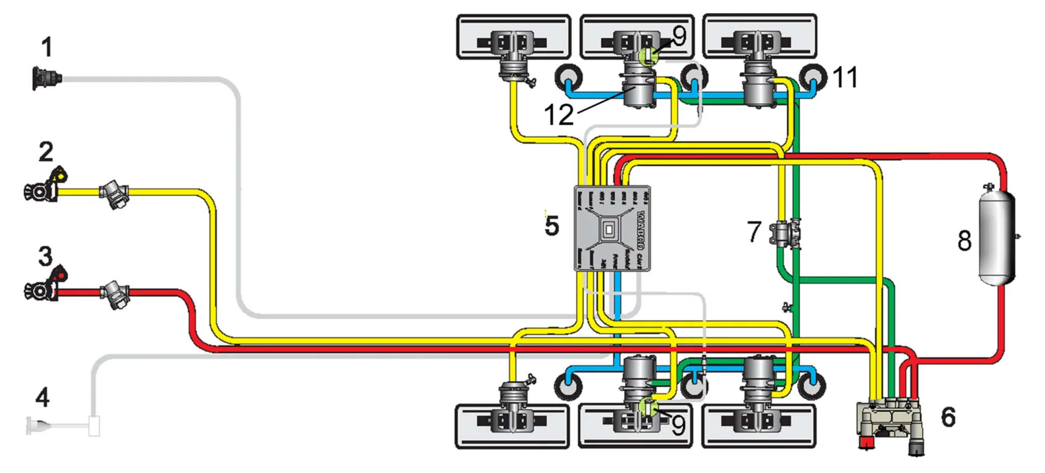
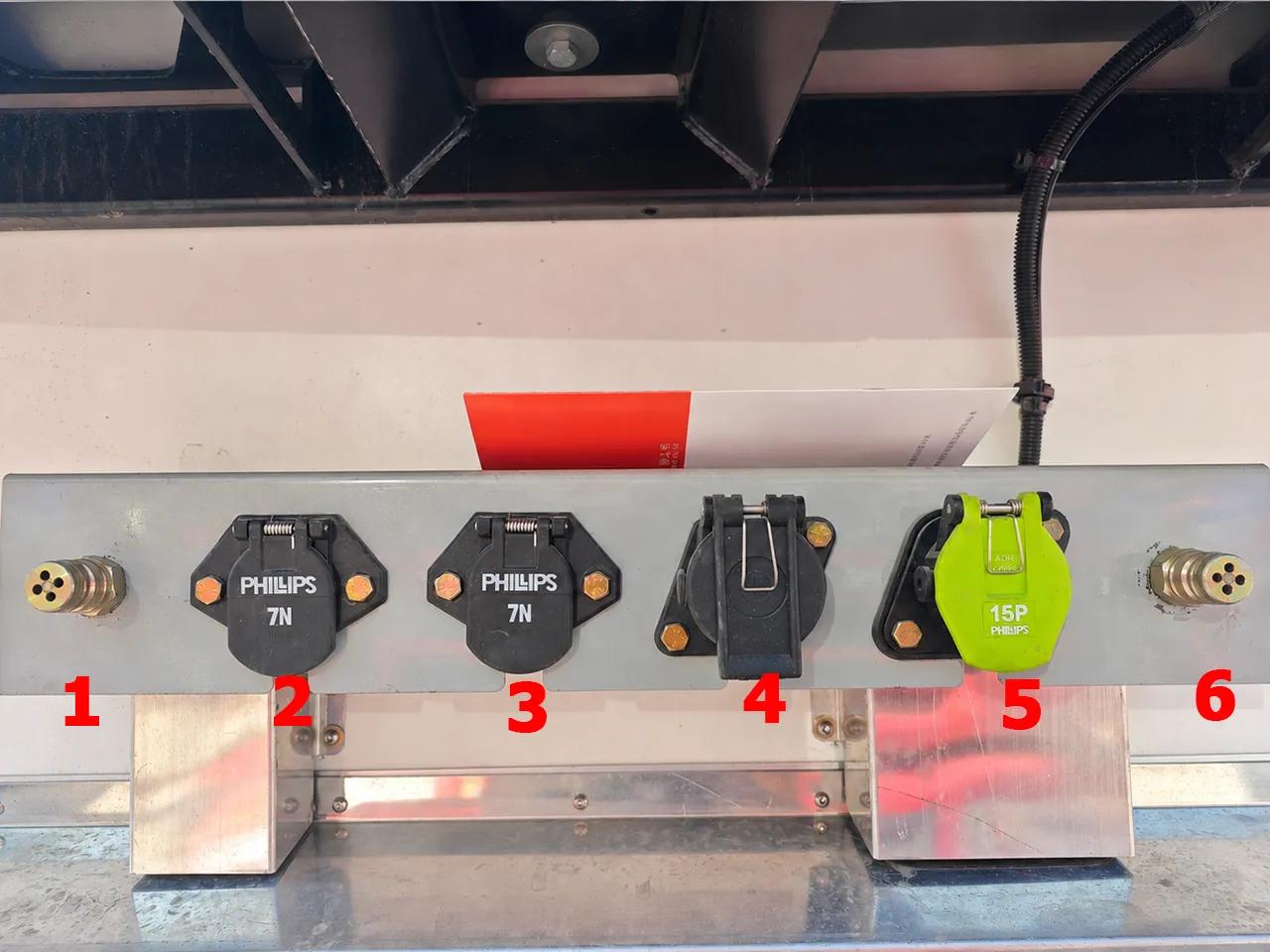
1. ISO 7638 Power Supply 2. Service Line (Control) 3. Supply Line 4. Stop Light Power (ISO 1185, Optional) 5. ABS/EBS controller 6. Release Emergency Valve 7. Quick release valve 8. Storage brake chambers 9. ABS Speed Sensor 11. Suspension Air Bag 12. Brake chambers
Note: In this diagram, the ABS/EBS controller already integrates the relay-valve delivery function. Please troubleshoot based on the actual installation of your vehicle model.
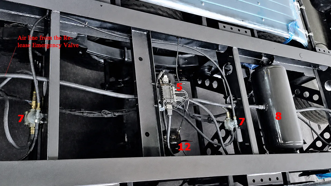
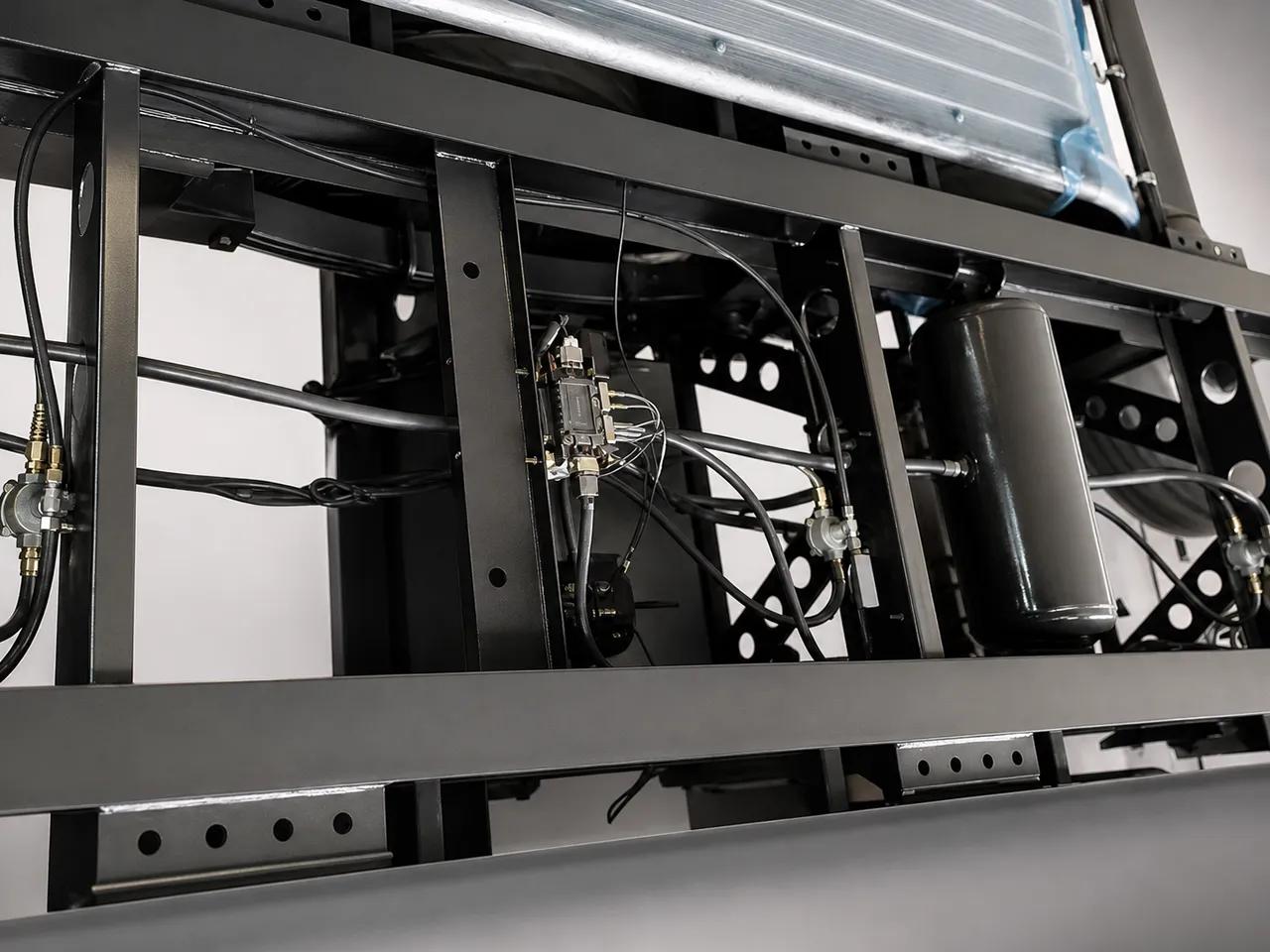
Annotated field photo showing where the ABS/EBS controller, Release Emergency Valve, quick release valve, brake chamber, and sensor cable sit on an actual semi-trailer axle group. Use it to match the schematic to the hardware before you start disconnecting lines or replacing valves.
Unlike a rigid truck, a semi-trailer has no compressor of its own. The trailer braking system is connected to the tractor via two specific coupling heads: one for supply pressure (3) and one for control pressure (2). The red supply line (3) charges the trailer’s brake chambers and keeps the emergency side alive, while the blue control line (2) carries the service-brake signal.
The Release Emergency Valve (6) acts as the central hub, transmitting the control pressure to the ABS/EBS controller (5). The Release Emergency Valve is equipped with two primary controls: a red operating button to actuate the parking brake, and a black operating button to release the brakes, a function that is automatically triggered when the trailer is uncoupled. Compressed air from the storage brake chambers flows through a non-return valve integrated within the Release Emergency Valve and enters the ABS/EBS controller (5).
Inside the trailer, supply air fills the storage brake chambers (8). When the driver brakes, the signal reaches the ABS/EBS controller (5), which controls the service brake components of the brake chambers (12). The system utilizes at least two ABS wheel speed sensors (9) to monitor wheel rotation. For maintenance, the pneumatic extension module also features a pressure test port to measure actual braking pressure.
To apply the parking brake, the operator presses the red button on the Release Emergency Valve. This exhausts the compressed air from the parking brake component of the brake chambers, allowing the internal springs to actuate the wheel brakes. If the service brake is simultaneously used, braking pressure flows through the anti-compounding valve into the parking component. This offsets the spring force in proportion to the service braking force established, ensuring that the two forces do not compound and cause mechanical overload on the wheel ends.
Component Logic: Standalone Relay Valve vs. Integrated EBS Modulator
| System layout | What you will usually find on the trailer | What it means for troubleshooting |
|---|---|---|
| Conventional pneumatic ABS trailer | Separate relay/emergency valve, quick release valve, chambers, and ABS hardware | Follow the air path component by component and test each valve body independently. |
| TEBS / EBS trailer with integrated modulator | ABS/EBS controller often combines electronic control, pressure modulation, and relay delivery logic | Do not search for a separate relay valve if the modulator already performs that job. Confirm the exact hardware layout first. |
| Mixed fleet workshop reality | Older trailers may use separate valves while newer export builds use integrated controllers | Start every diagnosis by identifying the installed modulator or valve assembly from the nameplate and air-line routing. |
The Three Primary Working States of the Trailer Brake System
To fully understand the troubleshooting process, we must recognize the three direct working states of the system:
- Normal Braking (Service Brake State): This is the most direct function we feel. When the brake pedal is pressed, the blue control line (2) sends air. The Release Emergency Valve (6) controls the delivery of air from the storage chambers (8) to the active brake chambers (12), generating braking force. When the pedal is released, the Release Emergency Valve (6) rapidly exhausts the compressed air from the chambers, quickly releasing the brakes.
- Charging Process (Feedback Braking State): If a trailer has been parked for a long time and the system has no air pressure, the spring parking brakes are active. When the tractor begins charging the trailer’s storage chambers (8) via the red supply line (3), the Release Emergency Valve (6) enters a safe braking state. In this safety state, the Release Emergency Valve initially sends compressed air directly into the brake chambers. Only when the pressure in the storage chambers (8) rises above 4.5 bar is this safety state released. This feedback braking function ensures the trailer generates braking force while charging, serving as a critical safety protection.
- Emergency Disconnect (Automatic Braking State): If the supply line (3) is accidentally damaged or disconnected, the compressed air stored in the trailer’s chambers (8) flows through the Release Emergency Valve (6) directly into the brake chambers (12). This automatically executes braking measures to ensure the vehicle’s safety in an emergency. This is the same principle you observe when the tractor intentionally disconnects the supply line when parking.
| Working state | What has pressure | What the mechanic should observe |
|---|---|---|
| Charging state | Supply line (3), storage chambers (8), release circuit | Trailer should progressively come off spring parking force as storage pressure rises. If not, check supply, PREV logic, and trapped parking pressure. |
| Service braking state | Control line (2), ABS/EBS controller (5), brake chambers (12) | Brake application should be even and fast across the axle group. Late build-up points to controller delivery, weak supply, or local leakage. |
| Emergency or breakaway state | Stored air routed by Release Emergency Valve (6) | Trailer must self-brake when the red line is lost. If it does not, stop operation and inspect the emergency valve path immediately. |
Trailer Storage and the UNECE R13 Reserve Rule
A trailer’s air storage within the brake chamber system is not just a tank. Under UNECE Regulation No. 13 for category O trailers, the trailer must keep braking even if the supply line is interrupted. In practice, that means the brake chambers, protection logic, and Release Emergency Valve must preserve enough usable air to keep the service brake effective after repeated applications.
Annex 7 defines the reserve by performance, not just by volume: after four full-stroke service applications with no recharging, the system must still be able to apply the brake a fifth time and deliver at least 50% of the prescribed service braking performance. For North American buyers, the FMVSS No. 121 shorthand is different but points to the same engineering logic: the trailer air storage volume must be at least eight times the combined volume of the service brake chambers (12) fed by that source.
In simple fleet terms, usable reserve depends on three things: storage volume, charge pressure, and air consumed per application. More volume and more usable pressure window give the trailer more stored stops. Higher leakage, chamber over-travel, or repeated full-pressure applications consume the reserve much faster.
Inspection takeaway: if water, oil carryover, or internal rust is reducing the effective volume within the brake chambers (8) or damaging seals, the trailer may still look “charged” on a quick yard check while already failing its real reserve requirement.ABS/EBS controller (5) vs. Quick Release Valve: Why Trailer Response Lives or Dies Here
On a semi-trailer, the ABS/EBS controller (5) and the quick release valve are not optional refinements. They are the components that let the trailer meet legal response-time behaviour.
What the ABS/EBS controller (5) does
The ABS/EBS controller (5) converts a relatively small control signal into a large, local flow of stored air from the brake chambers (8) into the active chambers (12). Without it, the trailer would have to wait for chamber fill through a longer and more restrictive air path, which slows actuation and reduces response consistency axle to axle.
What the quick release valve does
The quick release valve exhausts chamber air directly to atmosphere near the axle instead of sending that air back through the longer upstream path. This is why a healthy trailer releases cleanly and why a damaged quick release valve often shows up as dragging brakes, slow release, or hot drums/discs after a short road move.
Why the standards care about speed
UNECE R13 Annex 6 turns “fast enough” into a real pressure-time requirement. The response-time method uses a nominal 650 kPa input signal, with the reference signal rising linearly from 0 to 650 kPa in 0.2 s plus or minus 0.01 s. The trailer-side actuator pressure then has to build from 65 kPa to 490 kPa within the defined response interval. A sticking ABS/EBS controller (5), weak local supply, leaking chamber feed, or damaged quick release valve is one of the most common reasons a trailer fails this kind of test.
Coupling Lines, Breakaway Protection, and Why Red-Line Faults Are Critical
The most safety-critical trailer behaviour is automatic braking on breakaway or supply-line failure. If the red line is lost, the trailer must not simply coast free. The trailer valve (Release Emergency Valve) has to detect supply-line evacuation and trigger the emergency or spring-brake side quickly enough to stop the trailer from running away.
UNECE R13 clause 5.2.1.18.4 makes that behaviour explicit. When the supply line is evacuated at at least 100 kPa per second, automatic trailer braking must start before supply-line pressure falls to 200 kPa. When the designated control is fully actuated, supply-line pressure must fall to 150 kPa within two seconds. This is the formal basis for why cross-coupled lines, leaking gladhands, or a seized Release Emergency Valve are not small housekeeping issues – they directly compromise breakaway protection.
| Inspection item | Requirement or threshold | How to read it in the workshop |
|---|---|---|
| Stored-air reserve | Fifth application still delivers at least 50% braking performance after four full-stroke applications | If the trailer goes soft after repeated applications, suspect insufficient reserve in the brake chambers (8), excessive leakage, or bad protection logic. |
| Response signal | 0 to 650 kPa in 0.2 s plus or minus 0.01 s | Slow trailer response usually points to the ABS/EBS controller (5), feed, contamination, or valve-seat issues rather than a tractor complaint alone. |
| Actuator build-up | 65 to 490 kPa chamber build in the defined response window | If local chamber pressure rises late, inspect ABS/EBS controller (5) delivery and flow path first. |
| Breakaway start point | Automatic braking begins before supply-line pressure falls to 200 kPa | If the trailer does not self-brake on a red-line loss simulation, stop using it until the Release Emergency Valve and supply side are checked. |
| Supply-line drop on full actuation | Pressure falls to 150 kPa within 2 s | Slow evacuation suggests the wrong plumbing behaviour, sticking valve internals, or contamination. |
| FMVSS 121 trailer air sizing | At least 8 x combined service brake chamber volume | North American fleets can use this as a quick sizing check when comparing brake chambers (8) and chamber packages. |
Where Trailer Air Systems Usually Leak
Start with the system charged and the trailer brake applied. Work from the coupling heads inward and use a soap-bubble test on every suspect point. The loudest hiss is not always the true failure point, because sound can travel along pipe runs and cross-members.
| Leak or fault location | Typical symptom | Most likely root cause |
|---|---|---|
| Red or blue coupling heads / gladhands | Trailer will not charge, or spring brakes will not release | Worn seals, crossed couplings, damaged gladhand faces, or hose-end damage |
| Brake chambers (8) drain valve or tank shell | Pressure falls while parked; water drains heavily; rust flakes appear | Worn drain seal, trapped condensate, internal corrosion, or pitted shell |
| ABS/EBS controller (5) or quick release valve exhaust | Leak at the exhaust port; slow release; hot brakes after release | Damaged seat, contamination, aged diaphragm, or sticking spool |
| Brake chambers (12) | Pressure loss on application; one axle drags or under-brakes | Punctured diaphragm, pushrod over-travel, or damaged clamp / housing |
| Trailer relay-emergency valve (Release Emergency Valve) | No breakaway braking; poor charge behaviour; unstable release logic | Corrosion, frozen internals, distorted diaphragm, or supply-side contamination |
Fast Diagnostic Sequence by Symptom
| Field symptom | First check | Second check / do not assume first |
|---|---|---|
| Trailer charges slowly | Gladhands, red/blue line routing, tractor supply pressure | Then inspect Release Emergency Valve and storage chamber leakage. Do not start by replacing axle-end hardware. |
| Trailer drags after release | Quick release exhaust and residual chamber pressure | Then inspect ABS/EBS controller return, hose collapse, and slack-adjustment condition. |
| One axle runs hot | Compare chamber stroke and release timing axle to axle | Then inspect S-cam, return springs, and local hose restriction. Do not blame the lining set first. |
| Trailer will not move after parking | Confirm black release button position and charging pressure | Then isolate electrical lockup vs. trapped parking pressure vs. seized mechanical brake hardware. |
| Breakaway function fails | Stop service and inspect red-line logic immediately | Focus on Release Emergency Valve, emergency path, and supply-side evacuation behaviour before routine wear items. |
Mobile Field Checklist
- Trailer charges slowly: Check gladhands, red/blue line routing, and tractor supply pressure before moving to the Release Emergency Valve and storage-side leakage.
- Trailer drags after release: Check quick release exhaust first, then look for trapped chamber pressure, ABS/EBS controller return issues, or a collapsed hose.
- One axle runs hot: Compare chamber stroke and release timing across axles before replacing drums, linings, or other friction parts.
- Trailer will not move after parking: Confirm the black release button is in the release position and verify that charging pressure is actually reaching the trailer.
- Breakaway function fails: Stop operation and inspect red-line evacuation logic, Release Emergency Valve behavior, and the emergency air path immediately.
Use this list for phone-side field checks, then return to the full table when you need the second-step diagnostic path.
Semi-Trailer Air Brake Troubleshooting by Symptom
Now that we understand the structure, let’s look at actual, common faults in the field. Semi-trailer brake faults generally manifest as air leaks, dragging, or locking up.
1. Air pressure remains below 0.7 MPa for long periods, or the trailer experiences obvious brake dragging
How to resolve:
- Rule out the tractor: Swap the tractor unit with another one to completely rule out tractor-side air compressor or delivery faults.
- Soap bubble test: Use soapy water to pinpoint the leak source. Methodically check and eliminate leaks at gladhand connections, pipe joints, cross-leaking inside brake chambers, emergency relay valve exhaust ports, and ABS valve exhaust ports.
- Inspect for water/rust contamination: If the leak persists, check if the trailer valve bodies have water ingress or obvious rust. If this occurs, it indicates poor filtration and drying effects from the tractor’s air line. The internal seals are likely compromised, and you may need to replace the valve body.
2. Trailer is completely locked up after parking and cannot start/move
How to resolve:
- Isolate the electrical circuit: First, unplug the ABS spiral cable to see if the trailer can start normally. This rules out electrical or ECU-related lockup issues.
- Verify tractor supply: Ensure the tractor is in a pumping/charging state. Disconnect the air pipe at the hand control valve and check if the output pressure is normal. The pressure should be high during the charging state.
- Check Release Emergency Valve status: Confirm that the parking brake is actually in the released state. The black button on the Release Emergency Valve should be pushed in.
- Mechanical inspection: If the air circuit checks out fine with no issues, you must ultimately inspect the axles for internal mechanical faults, such as seized S-cams or broken return springs.
3. Trailer brakes apply but release slowly
This is classic quick release valve territory. A blocked exhaust, sticky diaphragm, or contaminated valve seat can keep chamber air trapped after the control signal drops. Also inspect the ABS/EBS controller (5) exhaust behaviour; a relay function that does not return cleanly can mimic a quick release fault.
4. One axle runs hotter than the others
Do not assume friction hardware first. Compare chamber stroke, local hose condition, and release timing on that axle. A local ABS/EBS controller (5) or quick release problem can keep one axle partially applied even when the rest of the trailer releases normally.
Field Note from Jason: We recently assisted a fleet where the rear axle brakes on a tri-axle trailer were consistently overheating. The fleet replaced the brake chambers twice with no success. A simple diagnostic pressure test revealed that the quick release valve’s internal diaphragm had hardened due to oil blow-by from the tractor, trapping 1.5 bar of residual pressure at that specific axle. Replacing the low-cost valve solved the larger repair problem. Always diagnose the air logic before throwing heavy parts at the trailer.
Common Misdiagnoses to Avoid
- Dragging brakes do not automatically mean the quick release valve is bad. A collapsed hose, seized S-cam, or over-stroked chamber can create the same symptom.
- Low system pressure does not automatically mean the ABS/EBS controller has failed. Start with tractor supply, gladhands, drains, and contamination first.
- A hot axle does not automatically mean friction parts are undersized. Compare pressure build and exhaust timing before replacing drums, discs, or linings.
- An ABS or EBS warning lamp does not automatically mean the pneumatic side is healthy or unhealthy. Electrical faults and air faults can overlap but they are not the same diagnosis.
- Replacing chambers repeatedly without checking upstream wet air usually treats the symptom, not the cause.
Why Moisture and Contamination Destroy Trailer Valves First
Many valve failures originate upstream in moisture and contamination brought in from the tractor. Water and oil entering the trailer’s brake chambers (8) corrode seats, seize spools, harden diaphragms, and freeze in cold weather. That is why the condensate drain, clean coupling heads, and routine inspection matter more than many fleets realize.
If a fleet keeps replacing ABS/EBS controller (5) units and quick release valves without addressing wet air and tank contamination, the new parts will fail the same way again. Clean, dry supply air is the foundation of the entire trailer circuit.
The Fleet Manager’s Preventative Maintenance (PM) Schedule
To avoid emergency breakdowns and extend the life of your ABS/EBS controllers and valves, integrate this simple checklist into your fleet’s routine:
| Interval | Action Item | Why it matters |
|---|---|---|
| Daily / Pre-Trip | Pull the reservoir drain valves (lanyards) for 3-5 seconds. | Expels overnight condensation before it reaches the ABS/EBS controller. If white or yellow emulsion comes out, the tractor’s air dryer is failing. |
| Weekly | Inspect red and blue gladhand seals. | Worn seals cause slow system charging and can trigger false breakaway braking. |
| Monthly | Perform a brake application and release timing test. | Listen for the crisp exhaust of the quick release valve. Sluggish exhaust means the valve diaphragm is sticking. |
| Annually | Replace the tractor’s air dryer cartridge. | Crucial for trailers: many trailer valve failures are caused by oil and water blow-by from a neglected tractor compressor system. |
What to Send Your Supplier or After-Sales Team
If you need remote support, the fastest way to avoid guesswork is to send a short but complete fault package:
- Trailer type, axle count, and whether it uses ABS only or TEBS/EBS.
- Nameplate photos of the ABS/EBS controller or emergency valve assembly.
- The exact symptom: slow charging, dragging, full lockup, one hot axle, or failed breakaway test.
- Whether the issue affects one axle, one side, or the whole trailer.
- Pressure readings taken at the supply line, control line, reservoir/test port, and chamber side if available.
- Photos or short video of the plumbing layout, valve exhaust behaviour, and warning lights.
Sources and Technical Basis
- UNECE UN Regulation No. 13, Rev.8, Amend.11 – trailer braking performance, response time, and reserve-air requirements.
- 49 CFR 571.121 (FMVSS No. 121) – trailer reservoir sizing, brake-chamber volume rule, and trailer-side air brake equipment requirements.
- KALES field inspection practice – soap-bubble leak checks, condensate drain inspection, and trailer-side response diagnostics.
Frequently Asked Questions
What is the difference between an ABS/EBS controller (5) and a quick release valve on a semi-trailer?
The ABS/EBS controller (5) delivers stored air quickly into the brake chambers. The quick release valve dumps chamber air locally so the brakes release quickly. One feeds the chambers; the other exhausts them.
Why does a trailer charge normally but drag after the driver releases the brake pedal?
The most common causes are a sticking quick release valve, an ABS/EBS controller (5) that does not return cleanly, or a brake chamber (12) or slack-adjustment problem that keeps one axle partially applied.
How should I troubleshoot a trailer that will not build pressure?
Start at the gladhands, hoses, and coupling seals. Then inspect the drain valve on the brake chambers (8), tank condition, Release Emergency Valve, and upstream protection logic. Do not jump straight to chamber replacement unless the leak clearly appears during brake application.
What does the FMVSS 121 reservoir rule mean in plain terms?
For trailers, each service reservoir, part of the brake chambers (8) system, must have a total volume of at least eight times the combined volume of the brake chambers (12) it serves. It is a simple way to check that the trailer stores enough usable air for safe braking.
Why is a leaking red-line coupling more serious than a normal service leak?
Because the red line is the supply and emergency side. If that path is compromised, the trailer may fail to charge correctly or fail to trigger the automatic braking behaviour required during breakaway or supply-line loss.
Final Recommendation
If a trailer will not build pressure, respond on time, or release cleanly, the right troubleshooting order is supply line, Release Emergency Valve, storage chambers, ABS/EBS controller, quick release valve, and brake chamber. For builders and fleet buyers, the engineering lesson is simple: stored-air capacity, emergency protection logic, local delivery, and local exhaust are one system. Underspec or neglect any part of that chain and the trailer will eventually show it under load.
Get Diagnostic Help for Your Trailer Brake System
If your trailer is charging slowly, dragging after release, locking after parking, or failing emergency-line behaviour, send the axle configuration, valve nameplate photos, pressure readings, and symptom video. KALES can help you narrow the fault path before you replace high-cost components blindly.