Foreword: Designed for professional drivers and fleet managers, this manual provides the essential SOPs (Standard Operating Procedures) for the safe operation of Kales Fuel Tanker Trailers. Adherence to these guidelines ensures compliance with international HAZMAT transport regulations.
1. Core Systems Overview
1.1 🛢️ Tank Body & Construction
- Material Standards: High-tensile Carbon Steel (Q345R), Stainless Steel, or Aluminum Alloy (5083). Compliant with ADR/RID and ISO standards for dangerous goods transport.
- Compatible Media: Gasoline (Petrol), Diesel, Kerosene, and Jet Fuel.ℹ️ Note: For transporting edible oils or specific chemicals, ensure seals (gaskets) and lubricants are food-grade or chemically compatible. Never cross-contaminate without validation.
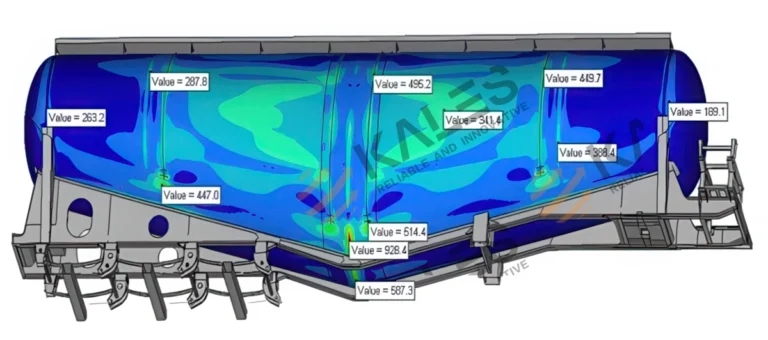
- Anti-Surge Design: Equipped with internal Baffles (Thickness ≥4mm, flow area >20%) to minimize liquid surge and improve vehicle stability.
- Capacity: 20,000L – 80,000L, available in Single or Multi-Compartment configurations.

- Cross-sectional diagram of the bulkheads and baffles in the Kales fuel tank semi-trailer

1.2 ⚙️ Manhole Assembly (Top Loading System)
Located on the tank top, the standard Euro-style Manhole (DN500) integrates:
- Breather Valve (P/V Vent): Dual-mode Pressure/Vacuum relief.
- Working Pressure: +6~+8 kPa (Pressure) / -2~-3 kPa (Vacuum).
- Emergency Venting: 21~32 kPa.
- Safety Interlock: The cover cannot be opened unless residual tank pressure is safe.
- Overfill Prevention: Integrated with optic/thermistor sensors to trigger high-level alarms and shut off loading automatically.

European-style manhole cover with integrated pressure 1.Overfill prevention probe 2.Vapor recovery valve 3.Gauging hatch (or dip tube opening) 4.Manhole cover with integrated Breather Valve and Safety Interlock
1.3 🔋 Bottom Loading System (API Standard)
The core system for closed-loop, environmentally friendly loading operations. Fully compliant with API RP1004.
- Emergency Foot Valve (Internal Valve): Pneumatically operated. Features a shear groove that snaps off during a collision, keeping the tank sealed to prevent spillage.
- API Adapter Valve: The standard 4-inch valve with a 70° nose angle for dry-break coupling. Uses FKM (Viton) seals for fuel resistance.
- Vapor Recovery Valve: Interlocked to open with the Foot Valve, returning volatile vapors to the terminal instead of venting to the atmosphere.
- Pneumatic Control Block: Centralizes control for all valves, including the Master Air Valve.

Valve Box Components Legend:
-
Master Air Valve: Activates the main pneumatic system.
-
Compartment Switches: Pneumatic controls for individual Emergency Foot Valves.
-
Vapor Recovery Switch: Opens the top vents (Interlocked with Master Valve).
-
Vapor Recovery Valve: Outlet for recovering vapors during loading.
-
Overfill Prevention Socket: Connection point for the terminal’s anti-overfill monitor.
-
API Adapter Valve: Standard 4″ connection for bottom loading/unloading.
-
API Valve Handle: Manually controls the valve opening and flow rate.
-
Static Grounding Pin & Clamp: Essential connection point for static dissipation.
2. Standard Operating Procedures (SOP)
2.1 ⛽ Loading Procedure (Bottom Loading)
A. Pre-Loading Checks
- 🛑 Park & Secure: Engine off, parking brake set, wheel chocks in place.
- ⚡ Static Grounding (CRITICAL): Connect the Bonding Cable to the terminal ground. Ensure the continuity light is green.*Wait 15 minutes after parking for static dissipation before connecting.
- 🔄 System Reset: Ensure all valves are closed and the air pressure gauge reads 0.35–0.5 MPa (50-70 psi).
B. Loading Execution
- Connections:
- Connect Overfill Probe Socket (Ensure no “Wet” alarm).
- Connect Vapor Recovery Hose.
- Connect Loading Arm to the API Adapter (Lock securely).
- Open Master Air Valve:
- ✅ Action: Pull the “Master” switch.
- 💡 Function: Engages the pneumatic system and forces the Vapor Vents open to balance tank pressure.
- Open Product Line:
- Actuate the Foot Valve switch for the specific compartment.
- Manually open the API Valve Handle.
- Start Loading: Follow terminal procedures. Monitor the Emergency Shut Down (ESD) button.
- Loading Sequence:
- Recommended: Load evenly (e.g., Center first, or Front/Rear balanced).
- ⚠️ PROHIBITED: Driving with a full load in only the front or rear compartment (prevents Kingpin/Suspension damage).
C. Post-Loading Disconnection
- Close & Disconnect: Once the pump stops, close the Foot Valve first, then the API Valve. Disconnect hoses.
- Final Step: Disconnect the Grounding Cable last.
2.2 💧 Unloading Procedure (Gravity Drop)
🛑 DANGER: Vacuum Collapse Warning
Liquid discharging creates a massive vacuum inside the tank.
NEVER unload without opening the Master Air Valve (Vapor Vents).
Failure to vent the tank will cause the tank body to implode (collapse) instantly.
Execution Steps:
- Hose Connection: Connect Vapor Hose (if available) first, then the Discharge Hose.
- Equalize Pressure: Open the Master Air Valve.Check: Listen for the “hiss” or mechanical sound of the Vapor Vents opening on top.
- Discharge: Open the Foot Valve, then open the Manual Discharge Valve.
- Monitor: Never leave the vehicle unattended. Watch the sight glass.
- Drain & Finish: Tilt the hose to drain residue into the storage tank. Close valves in order: Foot Valve ➔ Manual Valve. Disconnect hoses.
2.3 🚛 Special Operations
🔩 Lift Axle Operation
- Permitted: Only when the trailer is Unloaded (Empty).
- Prohibited: NEVER lift the axle when carrying a load.
↩️ Self-Steering Axle (Reversing)
- Procedure: Before reversing, drive forward 3–5 meters to straighten the wheels. Shift into Reverse and ensure the Locking Pin is engaged.
- ⚠️ Warranty Void: Reversing without locking the steering axle will cause severe damage to the steering mechanism and tires. This is NOT covered under warranty.
3. Maintenance & Safety Checklist
3.1 🛠️ Preventive Maintenance Schedule
| Component | Action Required | Frequency |
|---|---|---|
| U-Bolts | Re-torque after the first 50-100km (Loaded) to compensate for rubber settling. | New Trailer + Monthly |
| Static Grounding | Check the Earthing Strap for contact with the ground and conductivity. | 📅 Every Trip |
| Valves | Ensure all valves are fully closed. Do not leave in “Half-Open” position. | 📅 Daily |
| Pneumatics | Clean air filters/strainers. Check system pressure. | 📅 Weekly |
| Breather Valves | Professional inspection for sealing and pressure settings. | 📅 Quarterly |
| Extinguisher | Check pressure gauge (Green zone) and hose condition. | 📅 Monthly |
3.2 🚫 Critical Safety Rules
- No Overloading: Adhere strictly to the Gross Vehicle Weight (GVW) and compartment limits.
- No Ignition Sources: No smoking. Use only Non-Sparking Tools when working on the tank or valves.
- Confined Space Entry: NEVER enter the tank without: ① Full Depressurization ② Cleaning/Degassing ③ Forced Ventilation ④ Gas Testing ⑤ A Safety Spotter.
- Winter Precautions: If valves are frozen, DO NOT use open flames. Use steam or hot water to thaw.
This manual is based on the standard export configuration of Kales Vehicle Co., Ltd. Actual vehicle specifications may vary based on custom orders. Please refer to the technical documents delivered with your specific vehicle.